Selectric Resources
CHARACTER SELECTION OPERATIONAL THEORY
The purpose of the character selection mechanism is to position the typehead to print the desired character or symbol (Figure 1). At rest, the position of the typehead is such that the center character of the upper band is in the print position. If any other character is desired, the typehead must be tilted and/or rotated.
The character selection mechanism consists of two sections: tilt selection and rotate selection.These mechanisms transfer motion through their tape systems to tilt and rotate the typehead. The keyboard (see Keyboard Operational theory) starts the selection for the amount of tilt and rotate motion needed for each character.
The components of the character selection mechanism covered in this section tilt and rotate the typehead to the approximate character position. This is referred to as coarse alignment. Further positioning and locking of the typehead before printing is referred to as fine alignment and is covered in the Fine Alignment Section of this manual. The coarse alignment adjustments can be made with the rotate selection adjustment tool or the typehead. Both procedures are discussed later in this section.
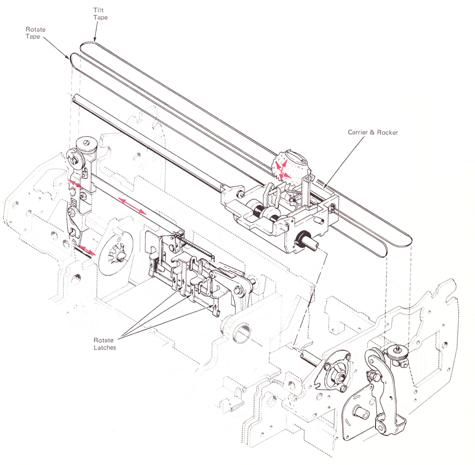
Figure 1 — Character Selection
CYCLE SHAFT AND LATCH BAIL
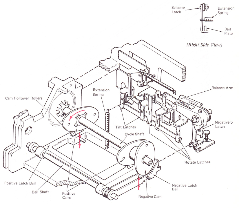
Drive is transmitted to the tilt and rotate mechanisms through three cams on the cycle shaft, the positive latch bail and the negative latch bail (Figure 2). The two positive cams operate together to control the positive latch bail. The negative cam controls the negative latch bail.
The positive latch bail pivots on the bail shaft at the front. Located at each side of the latch bail is a cam follower roller. An extension spring, at the rear of the latch bail, applies constant upward pressure to hold the follower rollers against the cycle shaft cams, Each time the cycle shaft operates, it rotates 180 degrees and the bail is forced down at the rear. Attached across the rear of the latch bail is the bail plate. The tip of the tilt and positive rotate latches are held at rest under the bail plate by extension springs.
The negative latch bail differs from the positive latch bail in that it rises when the cycle shaft rotates, but only if the negative 5 latch is pulled forward. This will be discussed later in this section.
The selector latches, which are components of the rotate and tilt mechanisms, determine how much rotate and tilt motion the typehead will receive, The two latches to the left control the tilting of the typehead, while the four on the right control the rotation of the typehead.
If the tilt and positive rotate selector latches remain to the rear, under the bail plate, they will be pulled down when the positive latch bail is operated. If any latch is held forward, it will not be pulled down during an operation of the latch bail. Pulling the various latches forward is discussed under the Keyboard Operational Theory Section.
 3
3
Figure 2 — Cycle Shaft And Latch Bail
TILT MECHANISM
The purpose of the tilt mechanism is to position the typehead vertically to any of the four character bands. This is done by transferring motion from the latch bail through a latch assembly, tilt arm, tilt tape, tilt bellcrank and a tilt ring to tilt the typehead.
TILT DIFFERENTIAL
Two tilt latches are attached at each end of a short lever by ball rivets (Figure 3). The ball shape of the rivets allows the latches to pivot in all directions. The lever is attached by a double vertical link to a bellcrank. The bellcrank pivots on a stud at the top of the differential bracket The connection of the double vertical link is not in the center of the lever, but is to the left so that one tilt latch receives two times the motion of the other.
A horizontal link connects the top of the bellcrank to the tilt arm. Operation of the bellcrank moves the tilt arm to the left to pull on the tilt tape.
The left-hand tilt pulley is mounted to the tilt arm on a ball shoulder pivot screw. This allows the pulley to remain horizontal when the position of the tilt arm changes. It must remain horizontal to prevent the tilt tape from coming off the pulley.
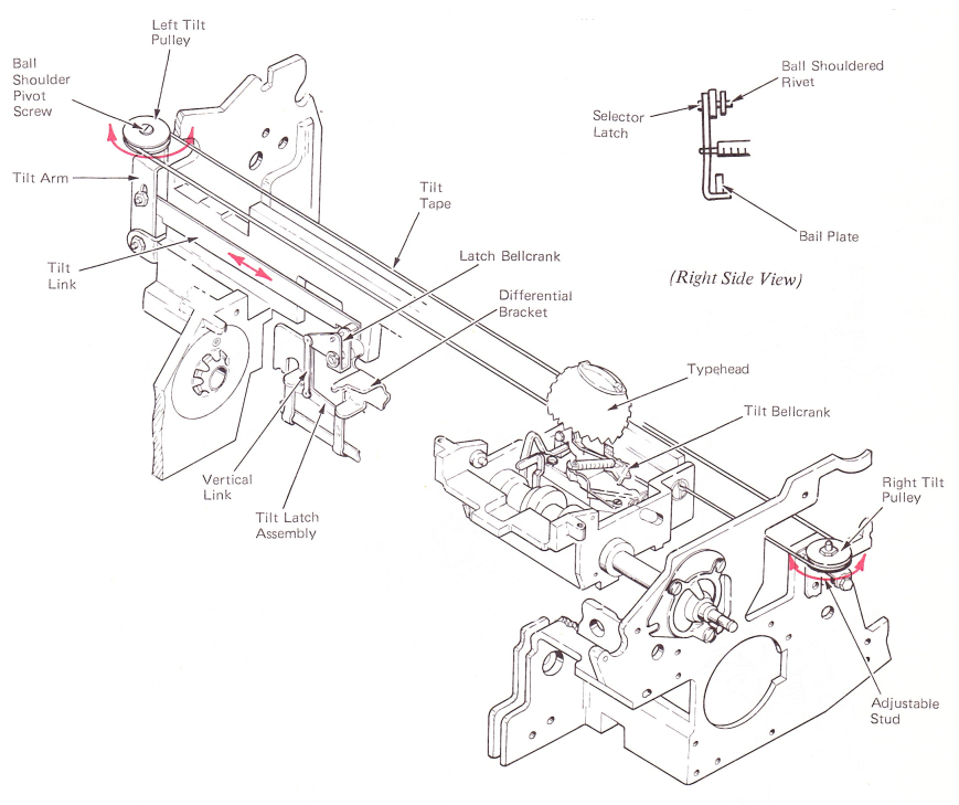
Figure 3 — Tilt Selection Mechanism
GEARLESS TILT (LEVEL 2)
Mechanical motion of the tilt differential is transferred to the typehead through the tilt tape (Figure 4). The tilt tape is connected to the tilt bellcrank on the rocker assembly. It extends to the left around the tilt arm pulley, back to the right around the right-hand tilt pulley, and is attached to the right side of the carrier. This arrangement allows left-to-right movement of the carrier without changing the tilt position of the typehead.
The right-hand tilt pulley is moved for adjustment only. The tilt arm pulley moves with the tilt arm. Movement of the tilt arm to the left pulls on the tilt tape, rotating the tilt bellcrank and causing the typehead to tilt.
GEAR TILT (LEVEL 1)
The level 1 mechanism uses two sector gears, a tube, and a pulley to control the tilt ring (Figure 4). As the tape is pulled, it rotates the tilt pulley which rotates the tube. A gear is mounted to the tube and is engaged with the tilt ring gear. Therefore, when the tube rotates, the tilt ring tilts.
TILT RING
Mechanical motion is transferred from the tilt tape and bellcrank through a link to the tilt ring (Figure 4). The tilt ring pivots on two pins between the yoke arms. A pull on the tilt tape causes the tilt ring to pivot about the pins, tilting the typehead. Because the typehead rests with the upper band of characters in the print position, all tilt operations are upward from the rest position. The tilt ring is restored to rest by an extension spring which connects to the tilt bellcrank.
NOTE: The tilt ring is discussed further in the Fine Alignment Section of this manual.
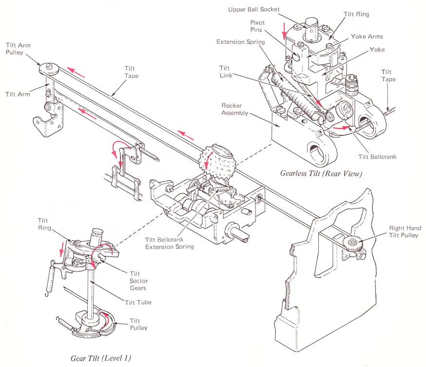
Figure 4 — Tilt Tape System
TILT 1 OPERATION
The tilt arm is rotated by a pull on the tilt latches. When the tilt 2 latch is held to the front while the tilt 1 latch remains to the rear, only the tilt l latch is pulled down by the positive latch bail (Figure 5). The link from the lever is then pulled to operate the tilt mechanism. This causes the typehead to tilt a distance of one band of characters, and places the second band from the top in the printing position.
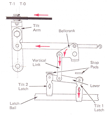
Figure 5 — Tilt 1 Operations
TILT 2 OPERATION
The same type of action occurs if the tilt 2 latch is pulled down by the latch bail while the tilt 1 latch is held forward. Operating only the tilt 2 latch (Figure 6) develops enough movement to cause the typehead to tilt a distance of two bands of characters. The third band is then in the printing position.
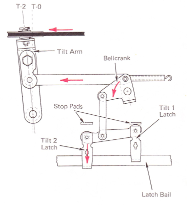
Figure 6 — Tilt 2 Operation
TILT 3 OPERATION
When both latches remain to the rear under the latch bail (Figure 7), both are operated. This causes the double vertical link to receive the same motion as the latches, resulting in three character bands of tilt. The fourth band is then in the printing position.
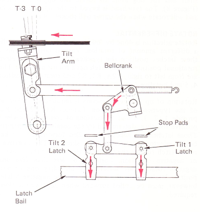
Figure 7 — Tilt 3 Operation
ROTATE MECHANISM
The purpose of the rotate mechanism is to position the typehead to any of the eleven rotational positions. The rotate mechanism is similar to the tilt mechanism except more latches and levers are required. Motion is transferred through the latch assembly, balance lever, rotate bellcrank, rotate link, rotate arm, rotate tape, rotate pulley, rotate shaft and the dog bone to rotate the upper ball socket (Figure 8). The typehead is keyed to the upper ball socket and will rotate when the upper ball socket rotates.
ROTATE DIFFERENTIAL
Rotate selection is done by four latches. Each latch supplies a different amount of rotation. Various combinations of these latches position the typehead to one of the eleven rotational positions. Each latch has a rotational value. They are from left to right, R2A, R1, R2 and rotational positions 4, 5 and negative 1.
Rotation of up to five characters is required on either side of the typehead rest position. Latches R1, R2 and R2A provide 1, 2, 3, 4 and 5 positions of counterclockwise or positive rotation, determined by the combination operated. Those latches not needed are pulled forward by the keyboard selector interposers (not shown). The negative 5 rotate latch rotates the typehead five units in the clockwise or negative direction. Positions of less than five units negative rotation are selected by including one or more positive latches with the negative 5. The negative 5 latch, however, must be pulled forward when negative rotation is required.
ROTATE TAPE SYSTEM
The rotate tape operation is similar to the tilt tape operation; however, the rotate tape transfers motion to rotate the typehead (Figure 8). The rotate tape is connected to the rotate pulley in the rocker, guided through the left side of the carrier, extended to the left around the rotate arm pulley, back to the right around the shift arm pulley, and connected to the right side of the carrier.
NOTE: The shift arm pulley moves only during a shift operation. (For more information on shift operation, refer to the Shift Section of this manual.)
When the rotate arm is moved away from the side frame, the rotate tape is pulled rotating the typehead in a counter-clockwise direction. When the rotate arm is moved toward the side frame, the typehead is rotated in the clockwise direction by allowing the rotate tape to wind around the rotate pulley under rotate spring tension.
The rotate spring is located below the rotate pulley and is in a fixed cage. The rotate spring cage is held in place by a retainer attached to the rocker casting. The outer end of the spring is attached to the cage and the inner end of the spring is connected to the rotate pulley hub. The rotate spring loads the rotate pulley in the clockwise direction.
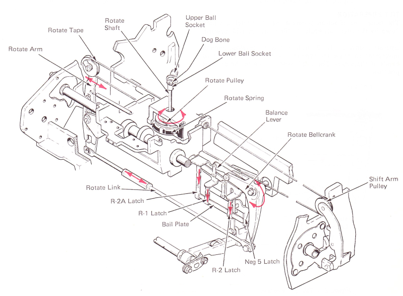
Figure 8 — Rotate Mechanism
POSITIVE ROTATION
The three selector latches involved in positive rotation are those to the far right under the positive latch bail. They are from left to right, R2A, R1 and R2.
The R1 latch is used for one- character rotation and the R2 latch for two-character rotation. With the R1 and R2 latches combined, as shown in Figure 9, a positive 3 rotate character will be selected, The R2 and R2A latches are operated for a four-character rotation. A five rotate character is received by pulling down the R1, R2 and R2A latches.
A balance lever at the center of the rotate differential is connected to the horizontal arm of the rotate bellcrank. The right end of the balance lever is held in place during positive rotation. A downward pull at the left end causes the rotate bellcrank to rotate counterclockwise. The rotate link connects the bottom of the rotate bellcrank to the bottom of the rotate arm. Counterclockwise rotation of the bellcrank causes the rotate arm to pivot about the fulcrum point and pull on the rotate tape.
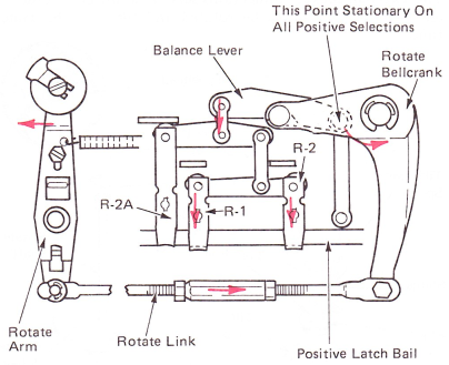
Figure 9 — Positive Three Rotate Operation
NEGATIVE ROTATION
Since positive rotation is performed by operating the rotate bellcrank counterclockwise, it follows that operating the bellcrank clockwise will rotate the typehead in the negative direction.
In order for the bellcrank to rotate clockwise, the right end of the balance lever must be raised. The right end of the balance lever has a flat link connection to the negative latch bail (Figure 10). The negative latch bail is a single arm located under the cycle shaft and pivots on the bail shaft. The bail has a cam follower roller located about the center of the bail. At rest, the bail is held down (inactive) by the high point of the right-hand cam on the cycle shaft. When the cycle shaft rotates and the negative latch bail is allowed to rise, the right end of the balance lever rises to allow clockwise operation of the rotate bellcrank.
The high point of the right-hand cam is 90 degrees from the high point of the other two cams. This ensures that when the positive latch bail is driven DOWN to the active position, the negative latch bail can be UP in the active position.
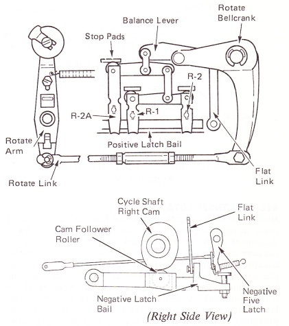
Figure 10 — Negative Latch Bail (At Rest)
The negative latch bail is prevented from rising during a positive rotate operation by the negative five latch (Figure 11).
The latch is mounted to the differential bracket and pivots front-to-rear. In the rest position, the latch is positioned above the head of an adjustable screw at the rear of the negative latch bail. During a positive rotate operation, as the cycle shaft begins to rotate, the bail moves up slightly and is stopped by the negative five latch. The slight amount of upward movement is allowed by the adjustment of the negative five latch screw and does not affect the positive rotate selection.
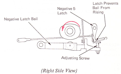
Figure 11 — Negative Latch Bail During Positive Rotate Cycle
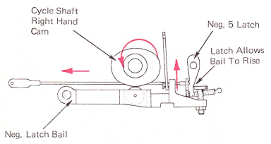
When the latch is pulled forward, the bail is allowed to rise (Figure 12). The force which raises the bail is applied by the rotate pulley spring and the extension spring attached to the rotate arm.
 (Right Side View)
Figure 12 — Five-Unit Bail During Negative Rotate Cycle
NEGATIVE THREE ROTATE
Movement of the negative latch bail from the latched-home point to the low point of the cam allows enough clockwise movement of the rotate bellcrank to allow a five-character negative rotation of the typehead. If less than five units of negative rotation is desired, it is necessary to pull down on the left end of the balance lever as the right end goes up. This reduces the amount of clockwise movement of the rotate bellcrank. Operating one or more positive rotate latches down while allowing the negative latch bail to rise, provides different amounts of negative rotation.The positive R1 and negative five combine to allow a negative four rotation. The positive R2 and negative five combine to give a negative three rotation (Figure 13). The positive R1 and R2 and a negative five operation allows a negative two rotation. And the positive R2 and R2A plus a negative five combination gives a negative one rotation.
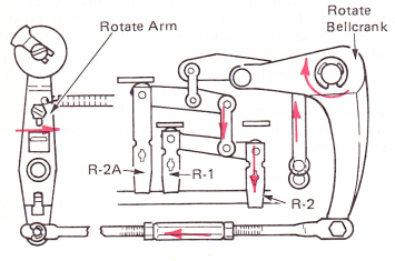
Figure 13 — Negative Three Rotate Operation
NEGATIVE ROTATE CHART
“Selectric”: Positive Latch + Negative Bail = Rotate Position |
|
0 |
-5 |
R1 |
-4 |
R2 |
-3 |
R1, R2 |
-2 |
R2, R2A |
-1 |
TYPEHEAD ROTATION
A clip holds the typehead to the upper ball socket, and a notch inside the typehead fits over a key which is pressed into the upper ball socket. This arrangement ensures that the typehead will rotate when the upper ball socket rotates.
The upper ball socket has a shoulder at the bottom which fits into the tilt ring (Figure 14). The fit is very close yet allows free rotational motion to the upper ball socket. The upper ball socket is held in place by the tilt ring spacer. The spacer is attached directly to the tilt ring and fits over a flange of the upper ball socket. Shims are used between the tilt ring and the tilt ring spacer to allow rotation of the upper ball socket. The shims also limit up and down play.
The bottom of the upper ball socket is hollow and forms the socket for a ball connection. A dog bone shaped ball fits into the socket over a pin that extends through the socket. The lower end fits over a pin in the lower ball socket. The lower ball socket is part of the rotate shaft. The rotate shaft operates directly inside the center of the yoke. Attached near the bottom of the shaft are the rotate pulley and rotate spring.
The two ball socket connections serve as a universal joint to allow the typehead to be rotated and tilted at the same time.
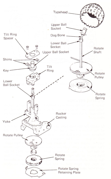
Figure 14 — Typehead Rotation
Any wear in the system will cause the typehead to drift in the negative direction. This is because of the rotate spring applying a constant pressure to the rotate system in a negative direction. Because of this drift, coarse alignment and homing adjustments should be checked each time the machine is serviced (Figure 15).
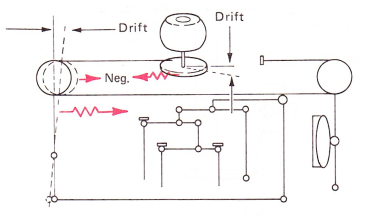
Figure 15 — Rotate System Drift
Early level machines used a wear compensator on the rotate arm (Figure 16). It has been found that drift in the rotate system is very limited and use of the compensator part of the rotate arm is not necessary. To prevent possible problems, the arm should be disabled as described at the end of this adjustment section.
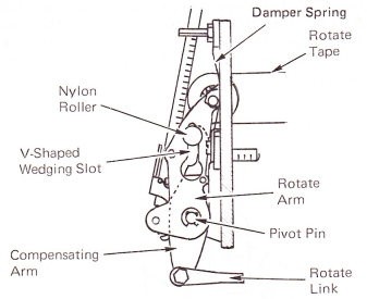
Figure 16 — Basic Components Of The Wear Compensator
Wear potential in the rotate mechanism is the way the rotate mechanism is able to properly align the typehead after a certain amount of wear is felt in the mechanism (Figure 17).
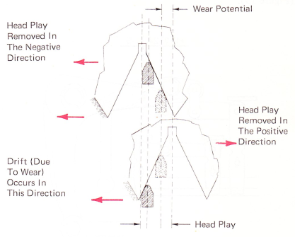
Figure 17 — Wear Potential (Rear View)
A part of the typehead play provides the rotate system with the large amount of wear allowed. To see how this is done let’s look at the relationship between head play, homing and bandwidth.
SELECTION OPERATION 96-CHARACTER "SELECTRIC" TYPEWRITER (W.T.)
The 96-character typewriter selection operational theory is nearly the same as the 88-character machine. There are some differences in the parts used. These differences are described in the following text and drawings.
The rotate system on the 88-character machine has 12 rotate selections available (+1 to +5, 0, +5, -5, -l to -5). Only 11 are used for selection. The +5 -5 is used to adjust the balance.
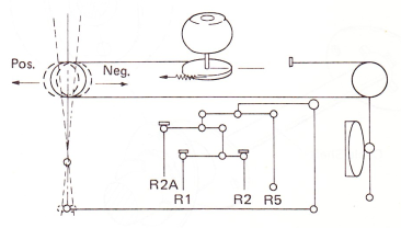
Figure 18 — Rotate Selection
On the 88-character machine the balance between positive and negative rotate direction can be seen by selecting the +5 and -5 position together. In this case the movement of the rotate bellcrank caused by the positive cams is lost by the opposite movement of the -5 unit cam and -5 unit bail; therefore, the rotate bellcrank is left in the same place (Figure 19).
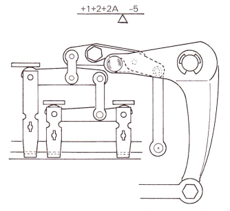
Figure 19 — Rotate Balance
Adding all the positive motion to all the negative motion is now used to get the -1 position on the IBM 96. To make this possible the negative selection cam is reduced only on its low part. This causes a higher movement of the -5 unit bail — now called the -6 unit bail — and the rotate system moves 1 position more in the negative direction (Figure 20). The positions -1 to -5 on the 88-character machine are changed to -2 to -6 on the IBM 96. Therefore, the 12 rotate positions on the IBM 96 are: +1 to +5, 0, -1, -2 to -6.
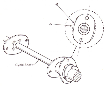
Figure 20 — Cycle Shaft
The rotate arm must move 1 position further to get to the -6 position. Therefore, to prevent the rotate arm from interfering with other parts during -6 operation, it must rest about 1 position more positive than on the 88 character machine (Figure 21).
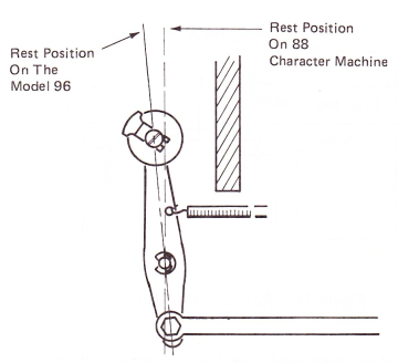
Figure 21 — Rotate Arm
UPPER BALL SOCKET, ROTATE LINK
It is simple to adjust the rotate homing; the upper ball socket is made of 2 parts that are mounted together with a screw (Figure 22). The upper part is called the single lug headholder. It has a lug that fits into the groove in the type element inner tube. The rotate homing is adjusted by loosening the screw and rotating this upper part of the upper ball socket,
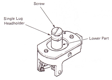
Figure 22 — Upper Ball Socket
Because the rotate homing is made by rotating the upper ball socket, the rotate link is now made of 1 part and the rotate arm rest position is not adjustable (Figure 23).
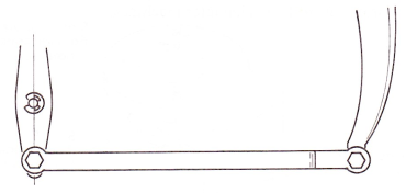
Figure 23 — Rotate Link
TYPEHEAD PLAY
Typehead play is the free motion in the typehead when the machine is at rest. It is due to the ball connection between the upper ball socket and the lower ball socket. The play is .050"-.060” (1.27-1.52 mm) measured at the typehead skirt or slightly less than half the distance between the teeth. The head play is distributed between the positive and negative sides of the typehead notch (Figure 24). The typehead is homed so the rotate detent contacts the side of the notch with the headplay removed in the negative direction, approximately .010”-.020” (0.25-0.51 mm) down the negative side of the notch.
The purpose of this adjustment is to provide maximum wear allowed to the system. Also, this adjustment allows more time to remove the detent before the typehead restores in the positive direction. Breakage in the system would occur if the detent was not removed before typehead movement begins.
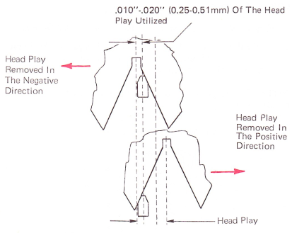
Figure 24 — Typehead Play And Homing (Rear View)
BANDWIDTH
With the head play removed in the negative direction, the most difference between detent entry of one typehead position (Figure 25A) and another typehead position (Figure 25B) is called bandwidth. It is caused by unequal adjustment of the rotate latch stop pads. You will note that we have now used up almost 3/4 of the negative side of the typehead notch.
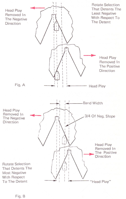
Figure 25 — Bandwidth (Rear View)
When the wear occurs in the system, the typehead drifts in the negative direction with reference to the detent. This causes the headplay and bandwidth to drift in the negative direction with reference to the detent. If this drift is not more than the headplay wear allowed, the detent will continue to fine align the typehead. When the wear allowed is more than the rotate selection that coarse aligns the most negative, the detent will fail to align the detent notch (Figure 26). The detent will fail to bottom causing that character to print out of alignment. The bandwidth and wear allowed must be kept as small as possible.
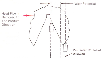
Figure 26 — Past Wear Potential Allowed (Rear View)
VERTICAL ALIGNMENT FAILURES
If there is a vertical alignment failure, first remove the typehead from the machine. Check the detent entry on the “z” and "j." Make sure the tilt ring is detenting properly when the play is removed in the negative direction, Also, be sure to check the entry by removing the play in the positive direction. This will tell if the tilt ring play is correct and, more important, if the detent is hitting on the tip of the notch. If the detent hits on the tip of the notch, the tilt detent will fail to bottom and it will keep the rotate detent from bottoming in the typehead tooth. This will look like a “fine alignment” problem, but it is a coarse alignment problem. If the tilt detent is not hitting the tip of the detent notch but it still fails to bottom, you may have a “fine alignment” problem (Figure 27).
Most problems in the tilt mechanism will show up as a vertical alignment failure on the paper. However, the tilt detent controls the rotate detent. If the tilt detent fails to bottom in the tilt ring, it is possible for the rotate detent to fail to bottom in the typehead. This could cause horizontal alignment failures on the paper.
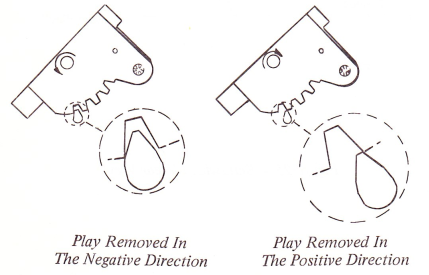
Figure 27 — Tilt Detent Entry (Left Side View)
ROTATE SELECTION ADJUSTMENT TOOL
The rotate tool provides a quick adjustment procedure that makes more exact adjustments possible. It can also be used to determine if a machine is within Engineering specification without a typehead (Figure 28). (This tool is not for use on W.T. 96-character machines.)
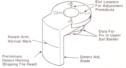
Figure 28 — Rotate Selection Adjustment Tool
HOW TO USE TOOL PROPERLY
To get the proper adjustment with the rotate adjusting tool, the following two conditions must be met:
1. No clearance exists between the blade of the rotate tool and the rotate detent (Figure 29).
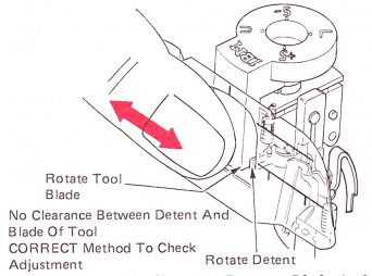
Figure 29 — No Clearance Between Blade And Detent
2. Detent should restore with no binds against the blade of the tool (Figure 30). Do not move the tool when checking this condition.
NOTE: Do not bias the tool in any direction when checking condition No. 2.
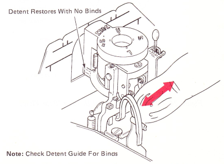
Figure 30 — Detent Restores Against Blade
Since the entry of the rotate detent is controlled by correct bottoming of the tilt detent, it is necessary that the tilt detenting be set up first.
7XX “Selectric” Typewriters equipped with the wear compensator cannot be adjusted with the rotate selection adjusting tool unless the compensator arm is disabled. Use the procedure at the end of the adjustment section.
CAUTION: It is possible for the blade of the tool to bind against the backup shoe on the tilt ring. Therefore, it will be necessary to remove the tool before half cycling the machine for every adjustment.
NOTE: The tool is for use with spring biased (slotted) tilt rings only.