Selectric Resources
KEYBOARD OPERATIONAL THEORY
The keyboard controls the selection of the particular character that will print. This is done through the use of keylevers, interposers and bails. which provide character selection and cycle clutch release (Figure 1). The keyboard is removable as a unit.
A keyboard lock mechanism, controlled by the on/off switch lever. is contained in the keyboard and will be described in this section.
All functional keylevers are described in their specific sections of this manual.
The keylevers pivot on a fulcrum rod at the rear. A guide comb holds and limits the vertical movement of the keylevers at the front. Keylever tension is supplied by flat leaf springs under the front of the keylevers. The forward end of each spring is formed so that the spring will remain under the keylever, Different spring tension is supplied to the four rows of character keylevers by auxiliary leaf springs under the keylever springs. The auxiliary leaf springs differ in length to make up the difference in tension between the four rows of keylevers. This difference in spring tension provides uniform operating force for all keylevers.
A keylever pawl is attached to each keylever by a shoulder rivet. This pawl is spring loaded and is in a position to contact the top of an interposer.
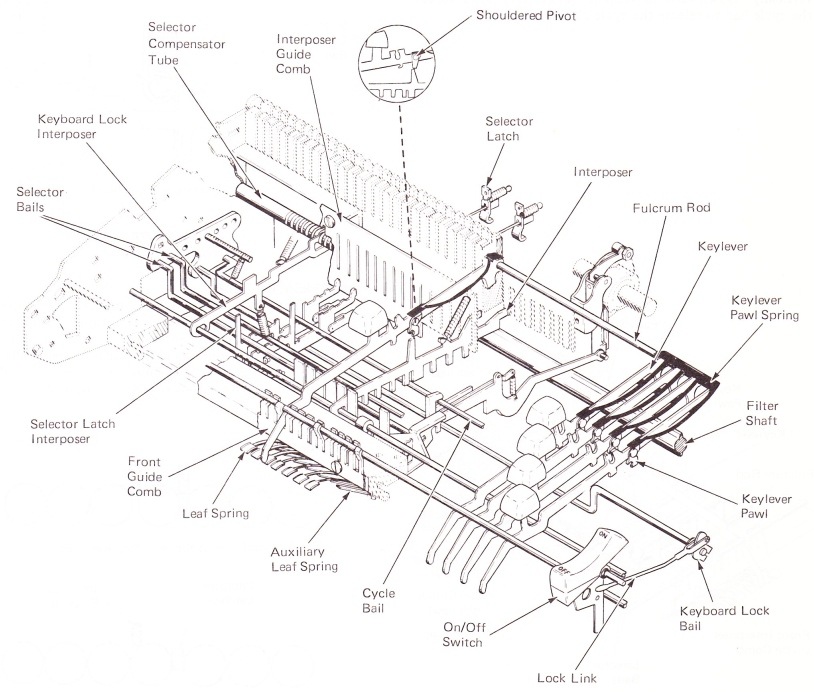
Figure 1 — Keyboard Mechanism
INTERPOSERS
Each character keylever has an interposer located just below it (Figure 2). The interposer is used to select the amount of tilt and rotate needed to bring the desired character on the typehead to the print position. The interposer pivots about a large fulcrum rod through an elongated slot at the front and is spring loaded up at the rear. The front and rear of the interposer is positioned laterally by guide combs. The interposers move vertically in the rear guide comb as well as front to rear.
The interposers have several lugs extending down from them (Figure 2). There are positions for eight lugs. Seven of these lugs are used for selection. The absence or presence of these lugs determines which of the selector bails will be operated. No two interposers are the same. The rear most lug is used for special applications of the machine. The wide lug in the center is common to all interposers. Its purpose is to release the cycle clutch when a keylever is depressed. Mounted directly below this lug is a cycle bail that pivots vertically. Downward movement of the interposer forces the cycle bail to release the cycle clutch latch pawl.
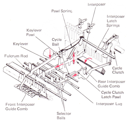
Figure 2 — Interposer
INTERPOSER LATCH SPRING
A spring latch is used to make sure the interposer remains depressed long enough to operate the character selection mechanism. The interposer latch is a flat spring mounted to the rear keylever guide comb in a position to move forward, holding the interposer down when it is depressed (Figure 3).
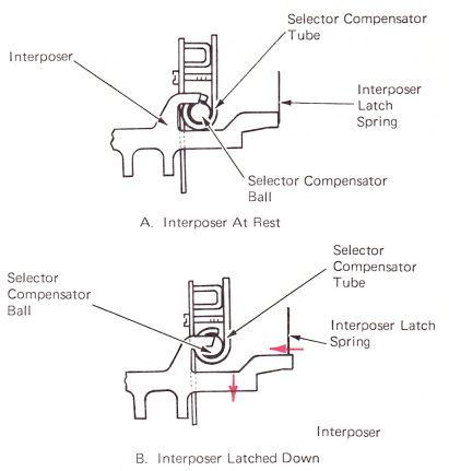
Figure 3 — Interposer Latch (Right Side View)
COMPENSATOR TUBE
A compensator tube is used to prevent more than one interposer from latching down at a time. Each interposer has a lug at the top that enters the compensator tube. The compensator tube contains closely spaced steel balls. When an interposer lug enters the tube, it shifts the steel balls, blocking the downward movement of any other interposer (Figure 4).
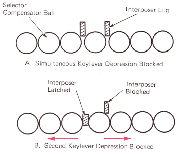
Figure 4 — Selector Compensator Action
An adjustable end plug, located at each end of the compensator tube, keeps the steel balls centered between the interposers. The balls are then prevented from shifting too far to the left or right. If the balls were allowed to move too far under the interposer lugs, they would partially block the downward movement of an interposer and result in a tight keyboard (Figure 5).
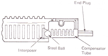
Figure 5 — Compensator Tube
SELECTOR LATCH INTERPOSER
Six latch interposers are located at the left end of the selector bails. Each latch interposer has a lug that extends up directly in front of the selector bail. As the selector bail is driven forward, the latch interposer is carried with it (Figure 6).
An adjustable link connects each latch interposer to one of the selector latches of the selection mechanism. When a latch interposer is moved forward. the selector latch connected to that interposer is also pulled forward to prevent it from being operated downward by the latch bail.
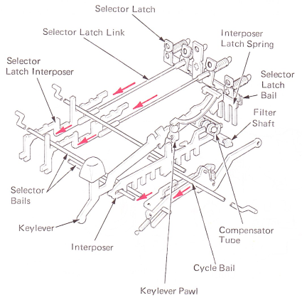
Figure 6 — Keyboard Selection Mechanism
CYCLE CLUTCH RELEASE
Although not a part of the keyboard, the cycle clutch latch is directly related to the keyboard mechanism (Figure 8). Downward movement of a keylever will allow the cycle clutch to operate.
The cycle clutch latch pivots on a bracket mounted in front of the cycle clutch pulley. The cycle clutch latch is held in position to engage the cycle clutch sleeve by the cycle clutch latch pawl and link assembly that extends forward from the cycle clutch latch. The cycle clutch latch pawl pivots on the cycle clutch link. The cycle clutch latch pawl engages the cycle clutch keeper to hold the cycle clutch latch under the step on the cycle clutch sleeve.
When a keylever is pushed down, the interposer below the keylever forces the cycle bail downward (Figure 8). The cycle bail moves the cycle clutch latch pawl down, disengaging it from the keeper. An extension spring at the front of the link is allowed to move the link and cycle clutch latch forward. disengaging the latch from the cycle clutch sleeve. This allows the cycle clutch spring to tighten and begin a cycle operation.
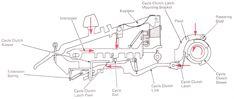
Figure 8 — Cycle Clutch Latch Release (Right Side View - Released Position)
CYCLE CLUTCH LATCH RESTORING
A nylon restoring cam attached to the cycle clutch clamp resores the cycle cluth latch (Figure 9). A horizontal extension at the top pf the cycle clutch latch has a small adjustable stud mounted on it which operates on the restoring cam during a restoring operation. When the machine is at rest, the low point of the restoring cam is directly below the stud. When the cycle clutch latch moves forward, the stud on the extension drops down on the restoring cam.
The restoring cam rotates toward the high point and forces the stud on the extension up, moving the cycle clutch latch to the rear into the path of the next step on the cycle clutch sleeve. The latch is restored far enough to the rear to allow the cycle clutch latch pawl to reset on the keeper.
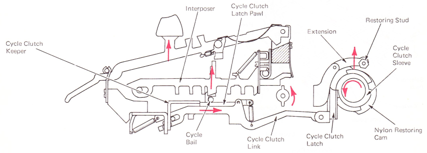
Figure 9 — Cycle Clutch Latch Restoring (Right Side View)
CYCLE BAIL DAMPERS (LEVEL 1 “SELECTRIC” TYPEWRITERS)
A small lever, called the cycle bail damper, pivots at each side of the keyboard just above the cycle bail (Figure 10). The purpose of the dampers is to lightly slow the upward movement of the cycle bail to prevent the bail from bouncing as it reaches the upward limit. Without the dampers, the bail could possibly bounce and cause an extra cycle of the cycle clutch.
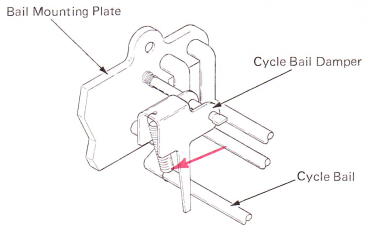
Figure 10 — Cycle Bail Damper (Level 1)
KEYBOARD LOCK
When the switch is in the off position, the keyboard must be locked to prevent a print operation the next time the switch is turned on.
The switch lever operates the lockout bail into a position below an extension of the cycle clutch latch pawl when the switch lever is in the off position. To further prevent an interposer from latching down, a linelock interposer at the left side of the keyboard is rotated into the selector compensator tube by the lockout bail. This forces the steel balls to shift in the tube and block the downward movement of all interposers. When the switch is in the on position, the linelock interposer is spring loaded out of the selector compensator tube (Figure 11).
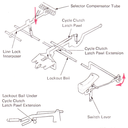
Figure 11 — Keyboard Lock Mechanism — Off Position (Right Side View)
96 CHARACTER “SELECTRIC” TYPEWRITER (W.T.) KEYBOARD ARRANGEMENTS (96 CHARACTER)
The keyboard has been designed to get the space for the added 4 keybuttons (shown in Red - Figure 12).
Carrier Return Key — Is smaller [6/8” (16 mm) wide] which allows space for type keybuttons in positions 45 and 46.
Express Backspace Key — ls located to the right side of the right shift keybutton.
Tab Key — ls reduced in size by removing the upper extension.
Shift Keys — The space for the shift keybuttons is smaller but the surface of the keybutton is similar in size to those on an 88 character machine.
The other functional keybuttons (backspace, index, and margin release) are only changed in size, but remain in the same place as on the 88 character keyboard.
The four new type keybuttons are located in positions 45-48. Positions 47 and 48 do not follow the normal sequence of the type keybuttons. Position 47 is to the left side of position 0, and position 48 is to the left of position 4. The repeat key(s), low velocity key(s) and dead key(s) positions are different in each country.
The design of the keyboard has been changed to allow these additional four keylevers. Also, other parts of the keyboard had to be changed. The parts are: front and rear keylever guides, front and rear interposer guides, compensator tube, keylever springs, interposer latch springs and the cycle bail damper springs. The cycle bail damper springs have been replaced by a flat leaf spring that is mounted to the cycle clutch latch keeper bracket. It has the same effect as the earlier dampers.
The correction feature is also compatible with this machine and the keybutton is in the same location as on the 88 character keyboard.
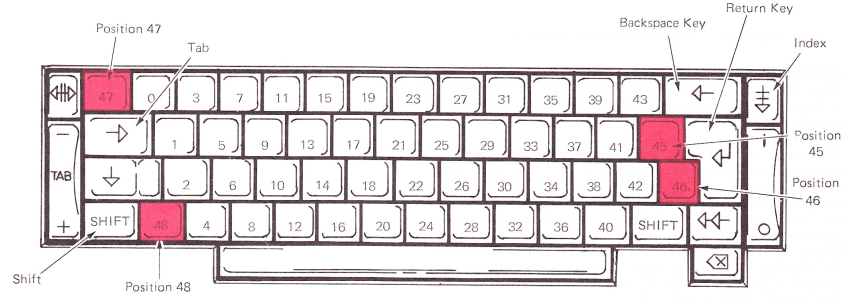
 Figure 12 - Keyboard Arrangement