Selectric Resources
FINE ALIGNMENT OPERATIONAL THEORY
Fine alignment refers to how the typehead is locked and supported in place during a print operation to ensure that the desired character prints clearly. This section will discuss how the typehead is locked into position for printing. The desired character is brought to the approximate print position in front of the platen by the selection mechanism. Just before printing, the tilt and rotate detents lock the typehead in position both horizontally and vertically. After the print operation occurs, the tilt and rotate detents are removed, allowing the selection mechanism to return the typehead to rest (Figure 1).
The carrier assembly is supported in front by the print shaft. The print sleeve is keyed to the print shaft, causing it to turn when the print shaft rotates. The print sleeve turns within two bearings in the carrier casting (Figure 1).
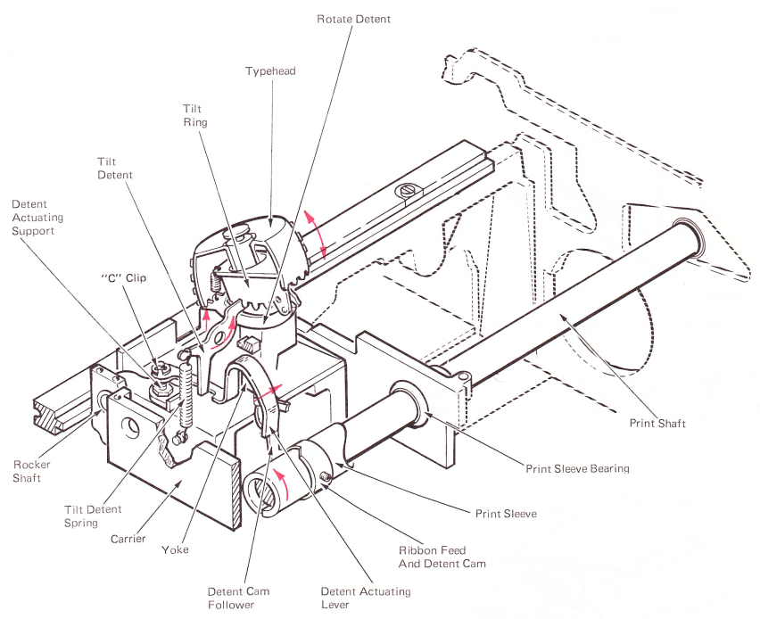
Figure 1 — Tilt And Rotate Detents
REAR CARRIER SUPPORT
The rear of the carrier is supported by the front edge of the escapement rack. A carrier shoe is mounted to the rear of the carrier. The front of the escapement rack fits into three lugs extending from the carrier shoe (Figure 2). A load spring, which is attached to the carrier shoe, maintains a constant pressure on the escapement rack, keeping any vertical play at the rear of the carrier to a minimum during a print operation.
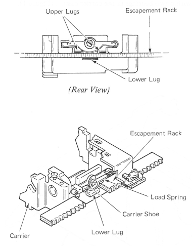
Figure 2 — Rear Carrier Support (Level 3)
Level 2 Machines — Two carrier shoes are used. A load spring is used to maintain a constant pressure on the upper carrier shoe and remove the play between the lower shoe and the bottom of the escapement rack (Figure 3).
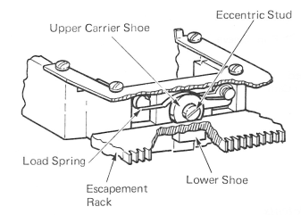
Figure 3 — Rear Carrier Support (Level 2)
Early Level Machines — The carrier has two shoes. The lower shoe is a small block attached to a plate and mounted on the carrier. The upper carrier shoe is mounted by an eccentric stud (Figure 4).
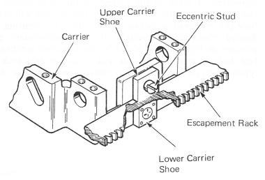
Figure 4 — Rear Carrier Support (Level 1) (No Load Spring)
ROCKER
The rocker is located in the rear of the carrier (Figure 5). The rocker assembly pivots about the rocker shaft.
Attached to the top of the rocker is the yoke (Figure 5). The yoke has two arms that extend up to provide a mount for two pivot pins. The pivot pins are adjusted to provide a tight pivot point for the tilt ring. Mounted at the top of the tilt ring is the upper ball socket to which the typehead is attached. The upper ball socket must be a tight fit with no binds. This is done by using shims under the tilt ring spacer.
The Level 2 tilt ring has an elongated hole to allow the upper ball socket to be spring loaded to the front of the machine, This keeps the tilt ring backup shoe in contact with the inside of the element providing a more constant print impact.
On the Level 1 tilt ring, the hole is not elongated to allow front-to-rear motion.
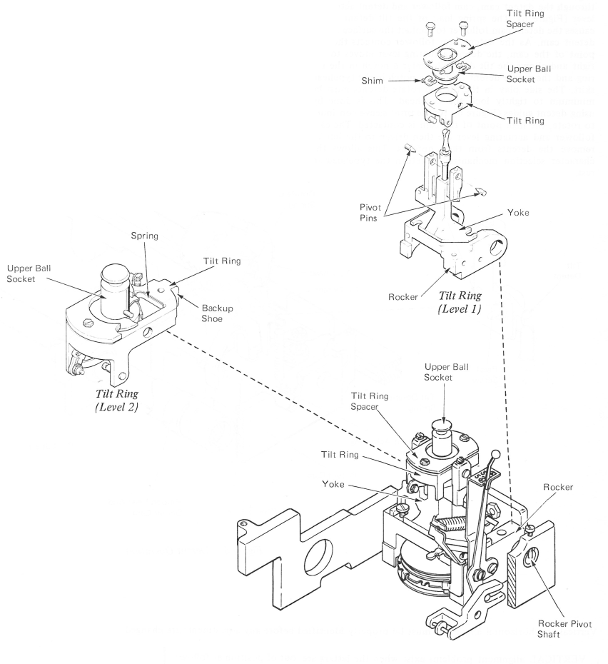
Figure 5 — Rocker Assembly
DETENT OPERATION
Motion to operate the detents is provided by the print sleeve which is keyed to the print shaft and rotates 360 degrees during each print cycle. This motion is connected through the detent cam, cam follower and detent actuating lever (Figure 6). The spring load of the tilt detent spring causes the detent cam follower to contact the surface of the detent cam. As the detent cam follower contacts the low point of the cam, the detent actuating lever moves to the right and allows the tilt detent to enter a notch in the tilt ring and the rotate detent to enter a notch in the typehead skirt. The side play in the tilt and rotate detents must be Guide minimum to tightly lock the typehead. This is done by using detent guides (Figure 6). As the print sleeve continues to rotate, the high point of the cam is contacted. The cam follower and actuating lever are then driven to the left to remove the detents from their notches. This allows the character selection mechanism to return the typehead to rest.
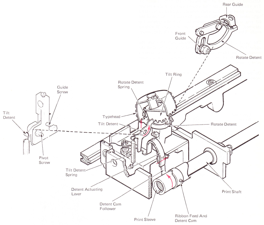
Figure 6 — Detent Operation
Vertical and horizontal alignment must be properly identified before any adjustments are changed.
VERTICAL alignment problems exist when the letters are out of position as follows:

HORIZONTAL alignment problems exist when the letters are out of position as follows:

96 CHARACTER “SELECTRIC” TYPEWRITER (W.T.)
The size of the IBM 96 type element is the same as an 88 character element. The IBM 96 type element uses two additional rotate rows of four characters each on the type element. Therefore, the rotate teeth are slightly closer together (Figure 7).
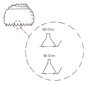
Figure 7 — Type Element
The positions of the tilt rows are a larger diameter on the type element to reduce side printing. Because of this, the tilt ring detent notches are closer together (Figure 8).
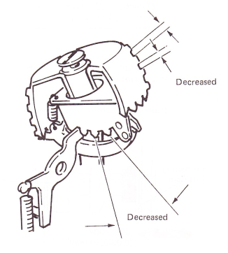
Figure 8 — Tilt Ring
The grooves in the inner tube of the type element are different. This serves as an interlock and will prevent the customer from putting a 96 character type element on an 88 character machine, and opposite (Figure 9).
The tops of 96-character type elements are colored gray to
show the difference.
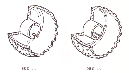
Figure 9 — Type Element Tubes