Selectric Resources
FINE ALIGNMENT ADJUSTMENTS
l. Carrier Shoe — Level 1 — Adjust the eccentric mounting stud to get .001”-.004” (0.03-0.10 mm) vertical play between the carrier shoes and the escapement rack.
NOTE: This amount of vertical play allows free horizontal movement of the carrier and limits vertical movement to help prevent difference in the vertical alignment of the type characters.
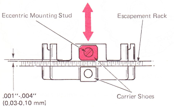
(Level 1 — Rear View)
Level 2 — Adjust the eccentric to get .002”-.006” (0.05-0.15 mm) vertical movement with the spring pressure removed.
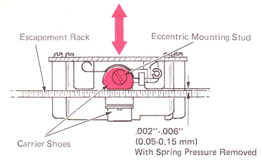
(Level 2 — Rear View)
Level 3 Parallel — Loosen mounting screw on carrier shoe. Press down hard on rear of carrier, keeping carrier shoe parallel with escapement rack. Tighten screw.
NOTE: On RB/S machines, ensure that the escapement pawl is centered in the escapement rack teeth.
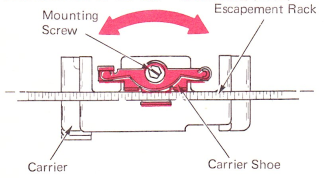
(Level 3 — Rear View)
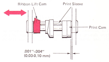
2. Print Sleeve End Play — The print sleeve must have .002”-.004” (005-0.10 mm) end play.
Level 1 Predual Impression — Tighten the setscrew in the ribbon lift cam into the hollow and then adjust the print cam left to right to get the print sleeve end play.
NOTE: Check rotational adjustment of print cam after making this adjustment.
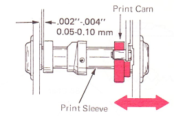
(Level 1 — Predual Impression) (Top View)
Level 2 Dual Impression — Adjust the ribbon lift cam left to right after the print cam setscrew is tightened into the locating hole in the print sleeve.
(Level 2 — Dual Impression) (Top View)
Correcting Machines — Ensure correcting lift cam is engaged in the ribbon lift cam dimple.
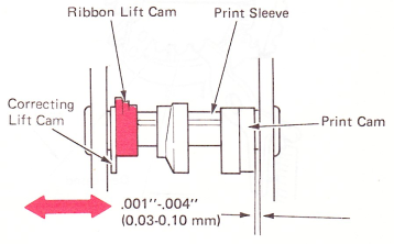
(Level 3 — Dual Impression Correcting) (Top View)
3. Rocker End Play — Adjust the rocker shaft left to right for minimum end play with no binds. The end play should exist between the “C” clip around the shaft at the right of the rocker and the thrust washer against the carrier casting at the left of the rocker. The rocker shaft is held in place by a setscrew at the left end of the rocker shaft in the carrier casting.
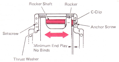
(Top View)
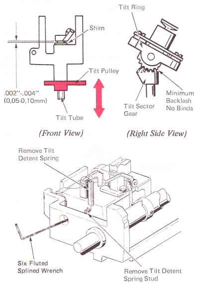
4. Tilt Tube End Play (Machines Before Gearless Tilt) — Adjust the tilt pulley vertically on the tilt tube to get .002”-004” (0.05-0.10 mm) clearance. The tilt tube pulley is attached to the tilt tube by a setscrew and a key against a flat surface on the tilt tube. The setscrew can be reached through a hole in the left side of the carrier. Move the carrier to the right and remove the tilt pulley spring and the tilt detent spring. The tilt detent spring stud can then be removed through the hole in the carrier. The height of the tilt section gear is adjusted by installing shims between the gear and the top of the yoke. This height is set to get minimum backlash with no binds between the tilt section gear and the tilt ring gear,
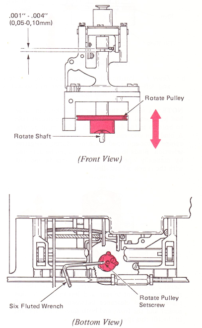
5. Rotate Shaft Clearance — Adjust the rotate pulley vertically to get .001”-.004” (0.03-0.10 mm) vertical motion of the rotate shaft. The rotate pulley is held to the rotate shaft by a wedging block and a setscrew. The pulley is reached from the bottom of the machine with the carrier centered over the cycle shaft and the machine in uppercase. DO NOT rotate the rotate shaft when the pulley is loose as this affects the rotate adjustment. Recheck typehead rotate adjustments after making this adjustment.
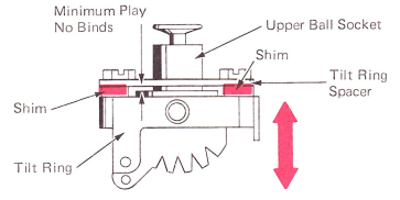
6. Upper Ball Socket —
a. Install shims between the tilt ring spacer so there is no vertical play in the upper ball socket, but it is still free to rotate.
NOTE: Vertical play in the upper ball socket will cause bad vertical alignment and impression because the typehead will not maintain an exact position when printing.
(Right Side View)
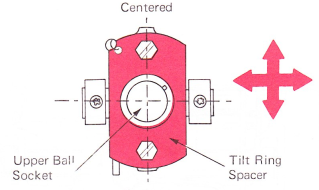
b. Level 1 — Position the tilt ring spacer front-to-rear and left-to-right so that the upper ball socket is centered in the tilt ring spacer.
NOTE: A bind in the upper ball socket can cause bad horizontal alignment if the rotate detent fails to bottom in the detent notch before print occurs. A bind can also cause the nylon roller to drop, on compensator-equipped machines, during a negative selection. Binds in the carrier area can be detected by manually operating the shift arm in and out with the typehead installed.
(Level 1 — Top View)
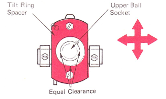
Level 2 Spring Biased Tilt Ring — Position the tilt ring spacer front to rear and left to right so that there is equal clearance between the upper ball socket and the front and both sides of the opening in the tilt ring spacer.
NOTE: To prevent malselection, all type elements used with this tilt ring must be lubricated with a light film of No. 23 or silicone grease on the inner surface.
(Level 2 — Top View)
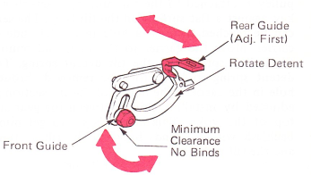
7. Rotate Detent — Adjust the front and rear rotate detent guides so the detent will operate vertically with no binds, but has no horizontal movement. Check this adjustment by half cycling a three tilt, zero rotate character and checking for rotational movement of the typehead. Excessive play in the rotate detent will cause bad horizontal alignment because the detent will not positively position the typehead.
On machines equipped with level 1 detent guide, this adjustment can be made with the tilt ring off of the machine. Loosen the front guide nut approximately a half turn to make sure that it will not interfere while adjusting the rear guide. Remove the rotate detent spring and adjust the rear rotate detent guide until a very slight amount of friction exists as the rear tip of the detent is moved up and down. It should be noted that the rear guide is on an angle and the closer the detent moves to the tilt ring, the tighter it will be wedged. Reconnect the rotate detent spring and adjust the front guide adjusting nut until it stops the rotate detent from being pulled to the bottom position by the rotate detent spring, then loosen the nut until the detent moves into place.
(Level 1)
NOTE: If you removed the tilt ring, do not reinstall at this time.
On machines equipped with the level 2 detent guide, the tilt ring can remain in the machine while making this adjustment. Loosen binding screw, then retighten lightly. Move the detent guide left or right until minimum side play and no binds exist between the rotate detent and the guide. Tighten the binding screw. The front guide is adjusted by the same procedure as the level 1 detent guide.
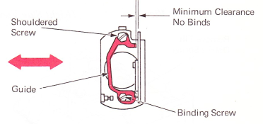
(Bottom View) (Level 2)
8. Tilt Detent — Adjust the guide screw and pivot screw so that the tilt detent pivots freely about the pivot screw with no side play. To do this, loosen both the pivot screw and the guide screw and disconnect the tilt spring and the rotate detent spring.
Adjust the guide screw so that no side movement is allowed when the tilt detent lever is operated past the guide screw. Adjust the pivot screw until it produces a very slight amount of friction on the tilt detent lever and tighten the locknut. Reconnect the tilt and rotate detent lever springs.

9. Tilt Ring — Adjust the pivot pins so that the tilt ring is centered in the yoke with no side play.
NOTE: On machines before the gearless tilt mechanism, caution should be taken to ensure that the tilt sector gears are properly matched when the tilt ring is installed. The rear tooth of the tube section gear should enter the second notch of the tilt ring sector gear.
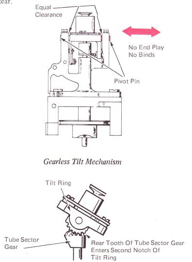
Gear/Tilt Mechanism (Right Side View)
10. Detent Cam Follower — Adjust the detent cam follower mounting bracket to satisfy the following conditions:
a. Front to rear for a clearance of .005”-.015” (0.13-0.38 mm) between the print sleeve and the end of the pin on the cam follower.\
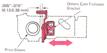
Front-To-Rear Adjustment (Right Side View}
b. Up or down so the rotate detent just begins to leave the typehead when the typehead has moved .020”-.040” (0.51-1.02 mm) away from the print position (high point of the print cam). Use a tilt 2, rotate 0 character to observe this.
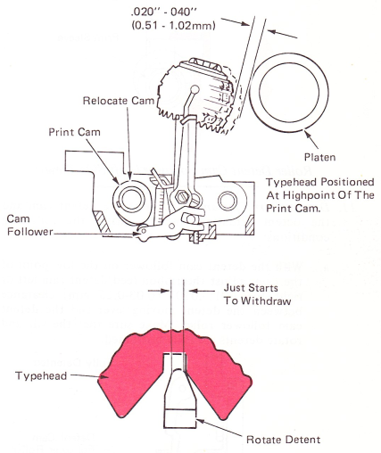
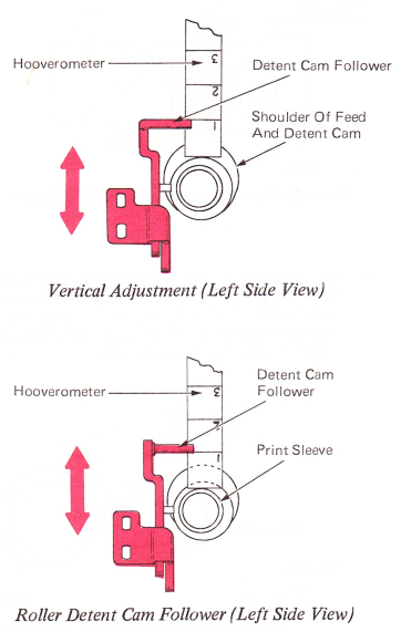
To get this condition, position the top of the cam follower so it is in line with the No. 1 line on the Hooverometer with the Hooverometer resting on the shoulder of the detent cam. Readjust as necessary to get the condition specified.
NOTE: Machines equipped with a roller on the detent cam follower should be positioned so the bottom surface of the pin is in line with the No. 1 line.
11. Detent Skirt Clearance — Adjust the detent cam and the detent actuating lever to satisfy the following conditions:
a. With the detent cam follower on the low point of the cam, adjust the ribbon feed/detent cam left or right for .001”-.010” (0.03-0.25 mm) clearance between the detent moving lever and the detent cam follower roller. Make sure that the tilt and rotate detents are fully bottomed.
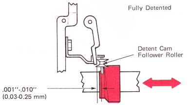
(Levels 1 & 2) (Top View)
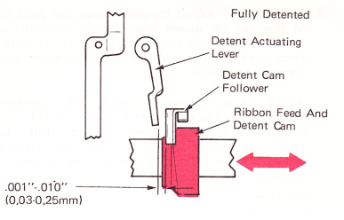
(Level 3) (Top View)
b. With the cycle shaft at rest and the typehead manually held at the tilt two position, adjust the detent actuating lever support screw up or down for .020”-.035” (0.51-0.89 mm) clearance between the detent and the teeth on the typehead skirt.
NOTE: These two adjustments may affect each other and both should be adjusted to get the correct clearances.
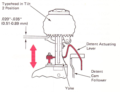
(All Levels) (Left Side View)