Selectric Resources
CHARACTER SELECTION ADJUSTMENTS
NOTE: Shift adjustments must be correct before beginning the coarse alignment adjustments. Remove the typehead before beginning adjustments.
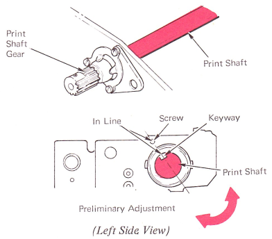
1. Preliminary Timing — Loosen the print shaft gear and rotate the print shaft so that its key slot is in line with the screw on the left side of the carrier casting. This coarse adjustment makes the detents operate at approximately the right time in the cycle.
2. Latch Bail Shaft — Adjust the bail shaft plate so that the bail shaft is parallel to the cycle shaft. Rollers should not clear the cycle shaft by more than .002” (0.05 mm).

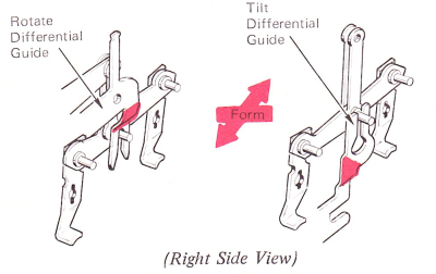
3. Rotate Differential Guides — Adjust the guides left and right so that the differential link is vertical.
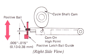
4. Positive Latch Bail Guide — Adjust the guide to get the following conditions:
a. Left and right so that the tilt and rotate latches are vertical.

b. Up and down (with the cycle shaft cams on the high point), so the positive bail lug will have .005”-.015” (0.13-0.38 mm) clearance from the bottom of the guide.
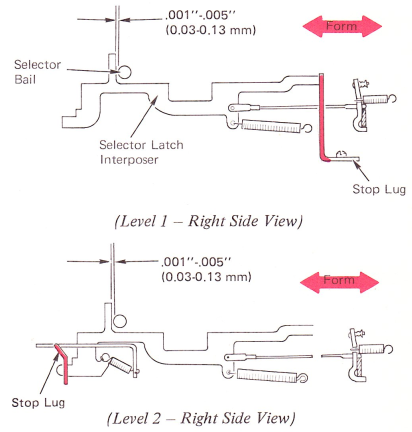
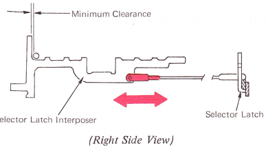
5. Interposer Stop Lugs (Levels 1 And 2) — Form the selector interposer stop lugs to get .001”-.005” (0.03-0.13 mm) clearance between each latch interposer lug and the selector bail. This adjustment establishes a fixed position for the interposers and will directly affect selector latch timing.
NOTE: This adjustment does not apply to late level machines. Refer to adjustment 6, Level 3.
6. Selector Latch Links
a. Level 3 — With the machine at rest, adjust the selector latch links so that the links just reach between the selector latches and the selector latch interposers. Then, make the link longer by 1/2 turn.
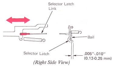
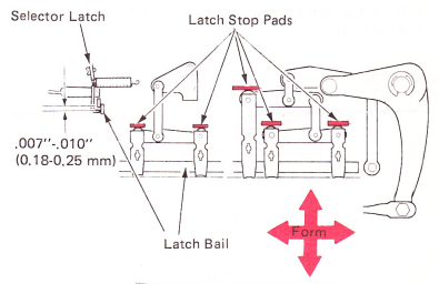
b. Levels 1 And 2 — With the machine at rest, adjust the selector latch links so that the tips of the latches overlap the bail .005”-.010” (0.13-0.25 mm). More or less overlap can cause the latches to pop out from under the bail causing malselection.
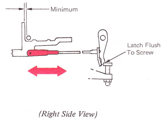
7. Negative 5 Latch Link 7
a. With the machine at rest, adjust the latch link so the link reaches between the negative 5 latch and its interposer. Then make the link longer by 1/2 turn.
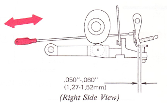
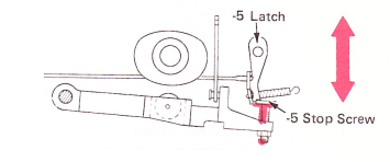
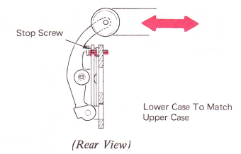
b. Early Level 7 With the machine at rest, adjust the negative 5 latch link so that the negative 5 latch will overlap the stop screw head by .050”-.060” (1.27-1.52 mm).
8. Latch Stop Pads — Form the latch stop pads to get .007”-.010” (0.18-0.25 mm) clearance between the latches and the positive bail with the positive bail on the low point of the cycle shaft cams.
The latches should reset under the bail at the same time.
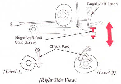
9. Negative 5 Bail Stop Screw — With the machine in the rest position, the negative 5 stop screw can be preset by turning it in until it bottoms and then by backing it out 1/2 turn. Ensure the cycle clutch latch pawl is in the window of the cycle shaft.
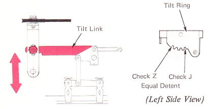
10. Tilt Arm Motion — Adjust the link up or down on the tilt arm so that the tilt ring will coarse align the same for a “Z” (tilt 0, zero rotate) as it does for a “J” (tilt 3, zero rotate).
11. Tilt Homing — With a “Z” (tilt 0, zero rotate) character half cycled and the tilt ring play removed in the negative direction (restoring direction), adjust the right-hand tilt pulley so the rear of the tilt ring will rise approximately .010” (0.25 mm) when the detent is manually allowed to bottom in the detent notch. As a further check, remove the tilt ring play in the positive direction and observe the detent entry on the forward side of the notch. The detent should enter far down the forward side of the detent notch, but not so far that it contacts the tip of the tooth.

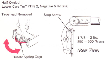
12. Rotate Spring Tension — Shift the machine into lower case and half cycle an “m” (tilt 2, -5 rotate). Adjust the rotate spring cage until a 1 7/8-2 pound reading is on the spring scale just as the shift arm contacts the stop screw. This is a CRITICAL adjustment. Excessive tension will cause extra wear in the system; not enough tension will not provide the torque necessary for quick lowercase negative rotate operations.
The rotate adjustments can be made using either of the following adjustment sequences. The first sequence (adjustments 13 through 22) requires use of the Rotate Selection Adjustment Tool. The last sequence (adjustments 23 through 31) requires use of the typehead.
NOTE: For W.T. 96-character machines, use adjustments with typehead.
ROTATE ADJUSTMENTS WITH TOOL
NOTE: When the term “half cycle” is used, the machine may be half cycled with the hand cycle wheel or the dynamic half cycle tool.
13. The compensator arm must be disabled. Use procedure at the end of this section.
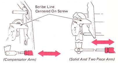
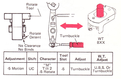
14. Rotate Arm Vertical — This is a preliminary adjustment and is made by adjusting the turnbuckle on the rotate link. Adjust the link so that the center of the top of the rotate arm is in line with the scribe line on the blade of the rotate tool. Tilt the machine in the service position and observe from the bottom of the machine.
NOTE: Check with machine at rest.
15. Preliminary Homing — Half cycle an UPPER CASE “I” (tilt 2, +3 rotate) with the carrier positioned over the cycle shaft area to aid in loosening the rotate pulley screw. Install the rotate tool with the pin on the upper ball socket located in the “U” (uppercase) slot in the rotate tool. Loosen the setscrew in the rotate pulley and then turn the tool in a clockwise direction until it touches the rotate detent and hold it in this position while tightening the setscrew.
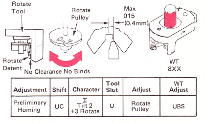
NOTE: This is the only time the tool will be used on this side of the rotate detent.
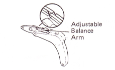
Machines with adjustable balance arms should have the balance arm positioned so that the notches are as shown.

16. Zero Rotate — With the machine in UPPER CASE, half cycle a “1/4” (tilt 2, zero rotate). Install the tool with the pin on the upper ball socket in the U slot of the rotate tool. Adjust the turnbuckle so that no clearance exists between the blade of the rotate tool and the rotate detent. Detent must restore with no binds.
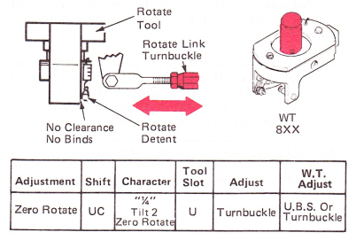
NOTE: Leave the turnbuckle loose at this time.
Remove tool.
17. +5 Motion — Half cycle an UPPER CASE “W” (+5 rotate, tilt 2) and install the rotate tool with the pin on the upper ball socket in the +5 slot of the rotate tool.
Adjust the link up or down on the rotate arm to remove all clearance between the blade of the rotate tool and the rotate detent without binding the detent.
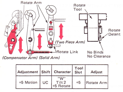
Remove tool.
18. -5 Motion — Half cycle an UPPER CASE “M” (tilt 2, -5 rotate) and install the rotate tool with the pin on the upper ball socket in the -5 slot of the tool. Readjust the turnbuckle to remove all clearance between the blade of the rotate tool and the rotate detent. The detent must restore with no binds. Tighten the turnbuckle nuts.
NOTE: Recheck this adjustment after tightening the turnbuckle nuts.
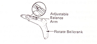
After adjusting the rotate link and tightening the lock nuts, ensure that there are no binds at the rotate link pivot points. This may be checked by moving the link front-to-rear and observing some link motion on the pivot studs. This will ensure that the flat ends of the rotate link are parallel to the flat ends of the rotate arm and rotate bellcrank.
Remove tool.
19. Balance — Half cycle an UPPER CASE “1/4” (tilt 2, zero rotate) and install the rotate tool with the pin on the upper ball socket in the U slot of the rotate tool. Adjust the -5 stop screw for no clearance and no binds between the blade of the tool and rotate detent.
Adjusting the -5 stop screw up decreases the clearance between the blade of the tool and the detent.

CAUTION: Be sure to check the overlap of the latch on the head of the stop screw. The head of the stop screw may be out-of-round and turning the screw may change the overlap.
NOTE: This adjustment is used for both the adjustable and solid balance arm. If the machine has an adjustable balance arm, the notches should be aligned as shown.
Remove tool.
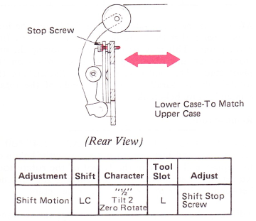
20. Shift Motion — With the machine in LOWER CASE, half cycle a “1/2” (tilt 2, zero rotate). Install the rotate tool with the pin on the upper ball socket in the L slot in the rotate tool. Adjust the shift stop screw in or out for no clearance and no binds between the blade of the tool and rotate detent.
Remove tool.
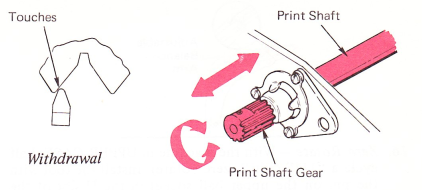
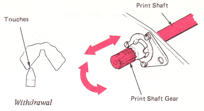
21. Final Timing — Replace typehead. Loosen the print shaft gear and advance or retard the print shaft so that the detent lightly scrubs the tip of the typehead tooth as it withdraws. Be sure to maintain .005”-.010” (0.13-0.25 mm) end play in the print shaft.
A method to get the above condition is to use the following procedure:
Loosen print shaft gear and cycle an UPPER CASE letter “M” (tilt 2, -5 rotate) until check pawl latches at half-cycle position. Manually rotate the print shaft, observe rotate detent entering and beginning to be removed. Stop rotation where the rotate detent is removed halfway from slope of tooth skirt.
Continue hand cycling operation until the type element begins to rotate. Stop hand cycling at this point. Tighten the print shaft gear.
CAUTION: Excessively advanced or late timing can cause parts damage as well as bad horizontal alignment or malselection. This could happen if the detent entered the wrong notch or remained in the notch too long.
NOTE: A burr on the print shaft may cause this procedure to fail. If previous fine timing adjustments have caused a burr on the print shaft, remove the print shaft gear and rotate it one tooth in either direction to get to a good surface of the print shaft.
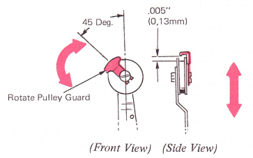
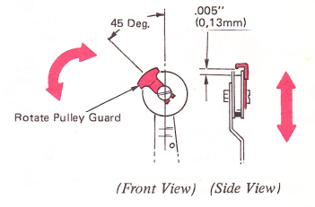
22. Rotate Pulley Guard — Adjust the rotate pulley guard around at 45 degrees left of vertical to keep the guard from hitting the power frame. The guard must clear the rotate tape by .005” (0.13 mm) with the rotate arm in the negative 5 position.
ROTATE ADJUSTMENTS WITH TYPEHEAD
23. The compensator arm must be disabled. Use the procedure at the end of this section.
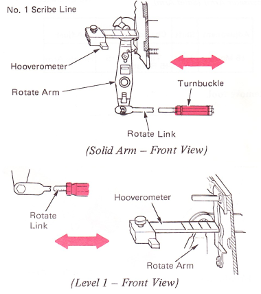
24. Rotate Arm Vertical (Preliminary) — Adjust the turnbuckle on the rotate link so that the center of the top of the rotate arm is in line with the No. 1 line of the Hooverometer when the Hooverometer is against the side frame.
NOTE: Adjustments 25 through 28 must be made with the machine in uppercase. Install the typehead.
25. Typehead Homing — Loosen the rotate pulley setscrew and slip the typehead around until the detent enters the correct tooth when a “T” (tilt 1, zero rotate) is half cycled. Set the detent in this tooth to about 1/3 down the negative side of the typehead tooth, with the head play removed in the negative direction. Tighten the setscrew. It is not necessary to slip the typehead if the detent enters the correct tooth.
On W. T. machines, adjust the UBS to get the above condition.
26. Rotate Arm Motion —
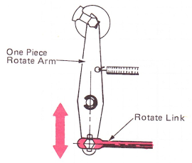
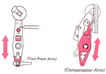
a. One Piece — Adjust the stud at the bottom of the rotate arm to provide the proper motion in each direction of typehead rotation. The correct position of the stud is determined by observing the detent entry of the “T” (tilt 1, zero rotate) and “W” (tilt 2, +5 rotate) while changing the stud’s position. When the detent entry is equal, the stud is correctly positioned.
b. Two Piece And Compensator Arm — Adjust the lower part of the rotate arm to provide the proper motion in each direction of typehead rotation. The correct position is determined by observing the detenting of the “T” (tilt 1, zero rotate) and “W” (tilt 2, +5 rotate). When the detent entry is equal, the lower part of the arm is positioned correctly.
NOTE: If the rotate link or the lower part of the rotate arm is adjusted to the upper limit and there is not enough motion, make sure the selection latch stop pads are adjusted correctly.
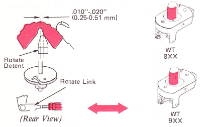
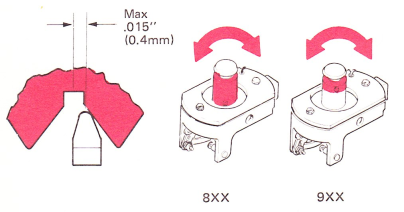
NOTE: W.T. 9XX machines should be adjusted to make the negative 6 rotate match the positive 5 rotate.
27. Balance — The -5 stop screw is adjusted for proper proportion between positive and negative selections. Make this adjustment by first cycling an uppercase “M” (tilt 2, -5 rotate) and observing detent entry. Next, half cycle a “T” (tilt 1, zero rotate) and adjust the -5 stop screw in or out until the detenting of the “T” (tilt 1, zero rotate) matches the detenting of the uppercase “M” (tilt 2, -5 rotate) previously observed.
Be sure to check the overlap of the latch on the head of the stop screw. The head of the stop screw may be out-of-round and turning the screw may change the overlap.
NOTE: If the machine has an adjustable balance arm the notches should be aligned as shown below.
28. Rotate Link — Adjust the rotate link so the rotate detent contacts the negative side of the typehead .010”-.020” (0.25-0.51 mm) from the center of the notch when the home character is half cycled.
W.T. — Adjust the UBS to get the above condition.
After adjusting the rotate link and tightening the lock nuts, ensure that there are no binds at the rotate link pivot points. This may be checked by moving the link front-to-rear and observing some link motion on the pivot studs. This will ensure that the flat ends of the rotate link are parallel to the flat ends of the rotate arm and rotate bellcrank.
NOTE: This adjustment should be checked on every call.
29. Shift Motion — Shift the machine into lowercase so that the shift arm contacts the stop screw. Adjust the stop screw so that a lowercase “t” (tilt 1, zero rotate) detents EXACTLY the same as an uppercase “T” (tilt 1, zero rotate).
30. Final Timing — Replace typehead. Loosen the print shaft gear and advance or retard the print shaft so that the detent lightly scrubs the tip of the typehead tooth as it withdraws. Be sure to maintain .005”-.010” (0.13-0.25 mm) end play in the print shaft.
A method to get the above condition is to use the following procedure:
Loosen print shaft gear and cycle an UPPER CASE letter “M” (tilt 2, -5 rotate) until check pawl latches at half-cycle position. Manually rotate the print shaft, observe rotate detent entering and beginning to be removed. Stop rotation where the rotate detent is removed halfway from slope of tooth skirt.
Continue hand cycling operation until the type element begins to rotate. Stop hand cycling at this point. Tighten the print shaft gear.
CAUTION: Excessively advanced or late timing can cause parts damage as well as bad horizontal alignment or malselection.This could happen if the detent entered the wrong notch or remained in the notch too long.
NOTE: A burred print shaft may cause this procedure to fail. If previous fine timing adjustments have caused a burr on the print shaft, remove the print shaft gear and rotate it one tooth in either direction to get to a good surface of the print shaft.
31. Rotate Pulley Guard — Adjust the rotate pulley guard around at 45 degrees left of vertical. This will keep the guard from hitting the power frame. The guard must clear the rotate tape by .005” (0.13 mm) with the rotate arm in the negative 5 position.
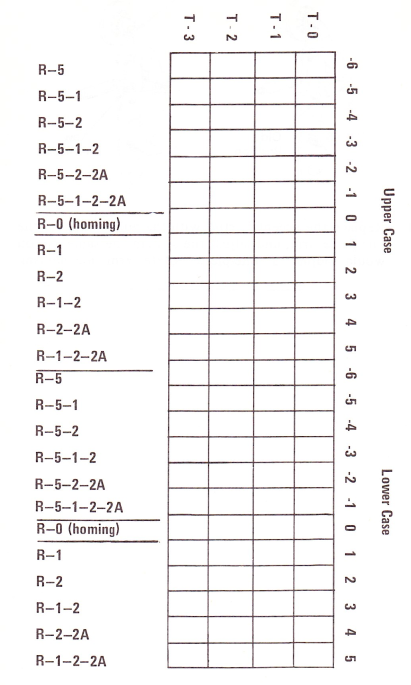
This completes the coarse alignment adjustments. The following chart may be used to determine the rotate and tilt locations of characters on typehead:
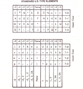
NOTE: W.T. — use chart below.
SELECTION ADJUSTMENT WITH ADJUSTABLE UPPER BALL SOCKET — W.T.
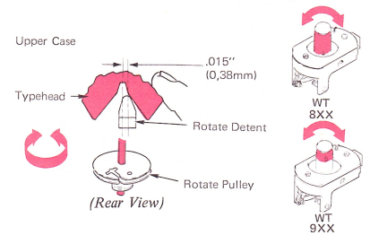
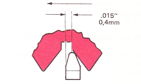
32. Typehead Homing — The rotate homing is adjusted for .015” (0.4 mm) clearance between center line of type element notch and center line of rotate detent with headplay removed clockwise.
a. To Adjust — Half cycle a tilt 2, +5 rotate character. Open the type element lever and loosen the upper ball socket screw. Move the detent actuating lever to remove the rotate detent from the notch. Push the type element down and rotate counterclockwise until rotate detent is even or past the center line of the first tooth.
b. Rotate type element clockwise while allowing rotate detent to slide up the side of the notch.
c. Continue rotating type element clockwise until center line of rotate detent is .015” (0.4 mm) from center line of notch.
d. Release detent actuating lever and allow type element to rotate counterclockwise until rotate detent bottoms in notch.

Hold type element down and prevent from rotating while upper ball socket screw is tightened. Check rotate detenting on tilt 2 rotate 0, -1, +5, -6.
NOTE: The lower ball socket and rotate pulley key have flats now. It is not possible to adjust rotate homing with the rotate pulley.
33. Balance Arm — Adjust for same element detent entry on tilt 2 rotate 0 as tilt 2 rotate -1.
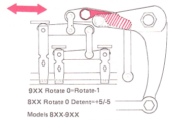
34. Rotate Arm Motion — Adjust the rotate link up or down for same type element detent entry on rotate +5 as rotate -6.
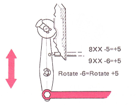
NOTE: Other adjustments remain the same as on the Model 82; for adjusting the rotate mechanism on Model 96, read -6 instead of -5.
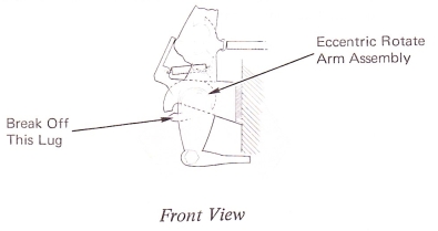
PROCEDURE FOR DISABLING COMPENSATOR-TYPE ROTATE ARMS
If there are problems in adjustment or operation of the compensator rotate arm, the following procedure can be used to change to a one-piece arm:
1. Carefully break off the lug on the bottom of the eccentric rotate arm assembly.
2. Place the wear compensator roller at the top of the slot.
3. Disconnect the spring from the rotate arm and connect it to the center of the compensator arm assembly.
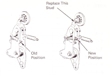
4. Replace the eccentric stud with the pulley stud for the one-piece arm, and adjust the system the same as you would adjust a one-piece rotate arm mechanism.