Selectric Resources
SPACE BAR ADJUSTMENTS
NOTE: All operational control adjustments must be correct before making any spacebar adjustments.
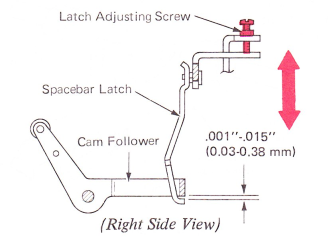
1. Operational Latch Height (NRB/S) — Adjust the latch adjusting screw so the spacebar latch will pass under the cam follower with a clearance of .001”-.005” (0.03-0.13 mm).
This clearance can be observed by pulling the latch to the rear with a springhook while the machine is at rest.
NOTE: Recheck interposer adjustingscrews adjustment — Operational Control Adjustment Section.
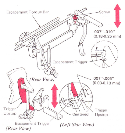
2. Spacebar Latch Lever Screw (NRB/S) — Adjust the screw so that .007”-.010” (0.18-0.25 mm) clearance exists between the escapement trigger and the escapement torque bar. Disconnect the escapement trip link before making this adjustment. The trigger upstop should be moved up out of the way when making this adjustment. After completing the adjustment, the upstop should be readjusted so it clears the trigger lever by.001”-.005" (0.03-0.13 mm) and is centered between the trigger restoring spring and the trigger mounting lug.
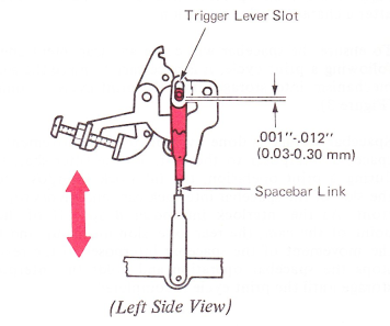
3. Spacebar Link (RB/S) — With the escapement trip link properly adjusted, adjust the spacebar link for .001”-.012” (0.03-0.30 mm) between the clevis pin and the bottom of the slot in the trigger lever.
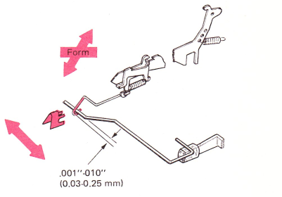
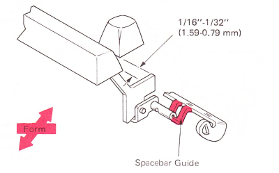
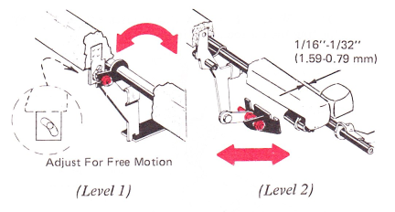
4. Spacebar Guide — Form the spacebar guide front-to-rear for free up and down motion of the spacebar keybutton and for 1/16”-1/32” (1.59-0.79 mm) between the rear edge of the spacebar keybutton and the front edge of the fourth row character keybuttons.
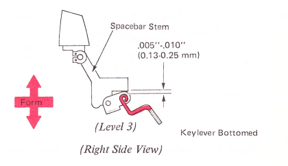
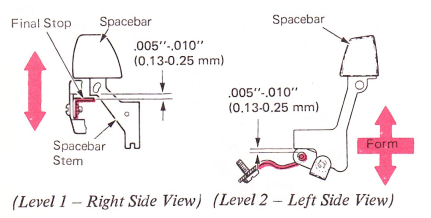
Form the spacebar guide up or down to get .005”-.010” (0.13-0.25 mm) clearance between the pivot shaft on the guide and the spacebar stem at the time the spacebar keylever is bottomed.
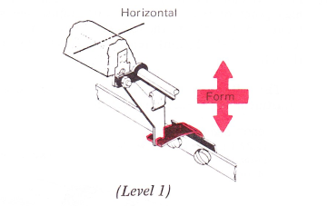
Spacebar Guide (Levels 1 And 2) — Adjust the spacebar guide for free motion.
5. Spacebar Return Spring —
Level 1 — The spring should be formed up or down so that a weight of 2-1/2 ounces (709 g) will just fail to release the spacebar interposer. The medium screwdriver, which weighs 2-1/2 ounces (70.9 g), can be used for this check.
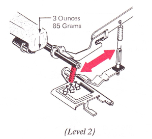
Level 2 — Position the spring on one of the three lugs on the carrier return/backspace repeat bail so that the spacebar can be released by a 3 ounce (85.1 g) load.
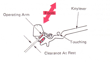
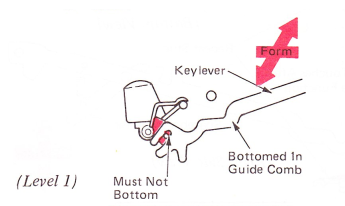
6. Spacebar Operating Arm (Level 1) — Form the spacebar operating arm to satisfy the following conditions:
a. Left to right so the operating arm overlaps the keylever by 0.30” (0.76 mm) minimum.
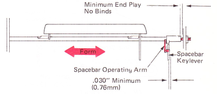
b. Up and down to provide clearance between the keylever and operating arm at rest.
c. Up and down to cause the keylever to bottom in the guide comb when the keybutton is fully depressed.
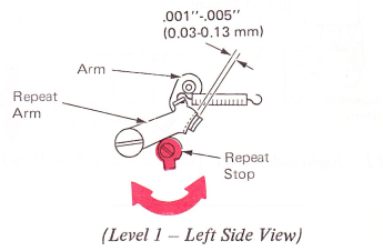
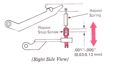
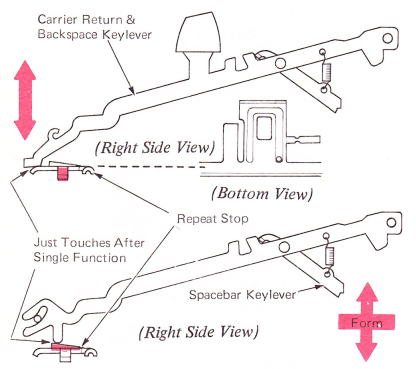
7. Spacebar Repeat Stop — The additional load of the repeat stop should be applied to the spacebar just after a single operation occurs. Adjust in the following way:
Level 1 — Adjust the repeat stop rotationally for a clearance of .001”-.005” (0.03-0.13 mm) between the arm on the spacebar shaft and the repeat arm when a single operation occurs.
Level 2 — Adjust the repeat stop screw for a clearance of .001”-.005” (0.03-0.13 mm) between the repeat stop screw and the repeat spring when a single operation just occurs.
Level 3 — Form the right lug so the carrier return and backspace keylevers contact the stop just after a single operation occurs. Form the spacebar lug so the spacebar keylever contacts the stop just after a single operation occurs.
8. Spacebar Final Stop — Adjust the spacebar final stop to get .005”-.010” (0.13-0.25 mm) clearance between the stop and the spacebar stem at the time a repeat operation occurs.
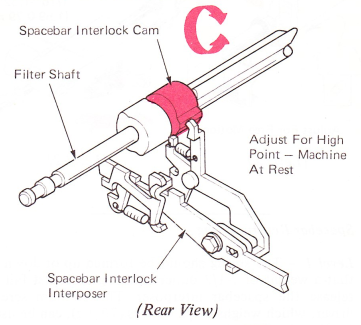
9. Spacebar Interlock Cam — Adjust the spacebar interlock cam rotationally on the filter shaft so that when the machine is at rest, the spacebar interlock interposer is on the high point of the cam.
NOTE: W.T. — For 9XX this adjustment is made by adjusting the escapement timing.
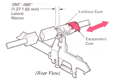
10. Lockout Cam (Level 1) — With the lockout cam on the high point of the escapement cam, adjust the escapement cam laterally so the lockout cam will have .050”-.060” (1.27-1.52 mm) remaining movement toward the left.
NOTE: Be sure to maintain the proper rotational adjustment of the escapement cam.
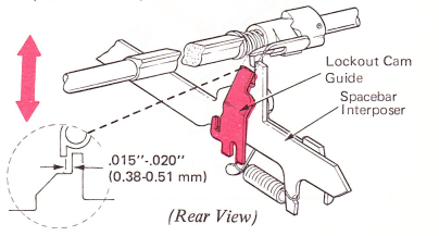
11. Lock Cam Guide (Level 1) — With a character half cycled, adjust the lockout cam guide up or down so the spacebar interposer will move to the rear .015”-.025” (0.38-0.64 mm) when it is unlatched.
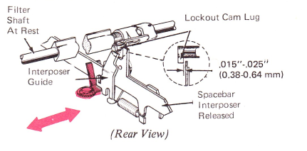
12. Spacebar Interposer Guide (Level 1) — With the filter shaft at rest and the spacebar interposer released, adjust the interposer guide left or right to get .015”-.025” (0.38-0.64 mm) clearance between the interposer and the lockout cam lug.
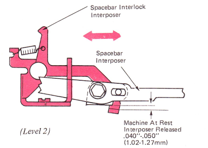
13. Spacebar Interlock Bracket — With the machine at rest and the spacebar interposer released, adjust the interlock bracket front-to-rear to get a clearance of .040”-.050” (1.02-1.27 mm) between the interlock interposer and the adjustable stop on the spacebar interposer.
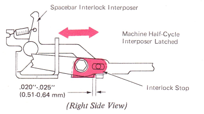
14. Interlock Stop — With the machine half cycled and the spacebar interposer latched at rest, adjust the spacebar interposer interlock stop so there is .020”-.025” (0.51-0.64 mm) between the interlock stop and the spacebar interlock interposer.
15. Space-To-Print Interlock — This adjustment only applies to machines equipped with a field installed space-to-print interlock.
a. With the machine tilted up, position the retaining clip so the space-to-print interlock extension is vertical.
b. Form the space-to-print interlock extension to clear the character interrupter bail by .001”-.010” (0.03-0.25 mm) with all parts at rest.