Selectric Resources
CARRIER RETURN OPERATIONAL THEORY
The purpose of the carrier return mechanism is to return the carrier to the left margin (Figure 1). The index mechanism is activated during each carrier return operation to line space the paper. The carrier return and index operations leave the carrier in position for printing at the beginning of the next line.
NOTE: The index mechanism is discussed in the Paper Feed and Index section of this manual.
During a carrier return operation, several things occur: the escapement torque bar is rotated to remove the escapement and backspace pawls from their racks; the carrier return spring clutch is activated to drive the carrier to the left margin; and the carrier return mechanism is latched in the active condition to ensure the carrier is driven to the left margin. When the carrier reaches the left margin, the mechanism is unlatched.
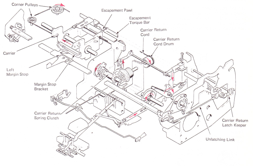
Figure 1 — Carrier Return Mechanism
CARRIER RETURN CLUTCH OPERATION
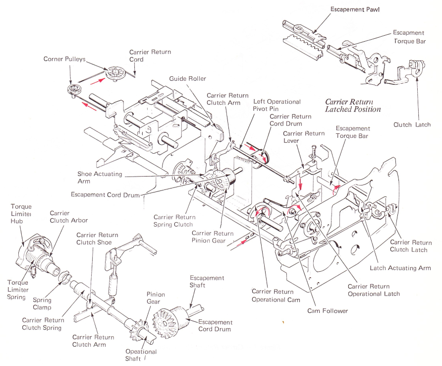
The power to turn the escapement shaft is taken directly from the operational shaft. The escapement cord drum has a gear on the front which engages a carrier return pinion gear on the operational shaft. A spring clutch is used to cause the carrier return pinion gear to rotate with the operational shaft. The pinion gear drives the escapement cord drum in a clockwise direction causing the carrier return cord to be wound on the drum (Figure 2).
The left-hand end of the carrier return pinion forms the arbor for the carrier return spring clutch. A second hub, the carrier return clutch arbor, is just to the left of the carrier return pinion. This hub is in constant rotation with the operational shaft and the carrier return clutch spring is attached to this hub by a spring clip. The operational shaft turns in the tightening direction of the spring; however, no drive occurs because the pinion hub is smaller than the inside diameter of the spring clutch. When the loose end of the carrier return clutch spring is pressed against the pinion hub, the spring clutch will tighten around the hub and drive the pinion. The tension of the spring clutch will return the clutch to the normal size when the external pressure is released.
The external pressure required to cause the carrier return spring clutch to drive is applied by a nylon shoe. The power to operate the nylon shoe against the clutch spring is taken from the carrier return operational cam. This cam has one cam surface and rotates 360 degrees during each operation.
CARRIER RETURN LATCHING
When the carrier return operational latch is pulled down by the cam follower, the latch pulls the carrier return lever down. As the carrier return lever moves down, it pivots the clutch latch shaft. Attached to the right-hand end of the clutch latch shaft is the carrier return clutch latch. As the carrier return clutch latch moves downward, it rotates the latch actuating arm which will pivot the escapement pawl from the escapement rack. The clutch latch and latch actuating arm are latched in their operational position (Figure 2).
The left-hand operational pivot pin is attached by setscrews to the carrier return lever and pivots about the mounting hole as the carrier return lever moves downward. Located on the left end of the left-hand operational pivot pin is the carrier return clutch arm. As the carrier return clutch arm moves upward, the carrier return shoe actuating arm pivots and forces the carrier return shoe into the spring clutch. The carrier return clutch latch causes the carrier return mechanism to be latched in this active position until the carrier reaches the left-hand margin. At that time, the clutch is unlatched and the escapement pawl is allowed to restore into the rack (Figure 2).
CARRIER RETURN UNLATCHING
When the carrier reaches the left margin, the carrier return clutch must be unlatched and the pawl returned to its rack, ready for the next operation. This is done through the linelock bracket which transfers motion from the carrier through the margin rack to unlatch the carrier return arm assembly (Figure 3).
When the carrier is away from the left margin, a compression spring, located at the left end of the margin rack, loads the rack to the right. As the carrier is returned to the left margin, the linelock bracket strikes the left margin stop, forcing the margin rack to the left. Motion is then transferred through the overbank guide, a bellcrank, and an unlatching link, to pull the latch keeper forward, unlatching the carrier return arm assembly. As the carrier return arm unlatches, the escapement torque bar will return to rest, allowing the pawl to return to its rack. The nylon shoe will also return to rest, disengaging the carrier return clutch.
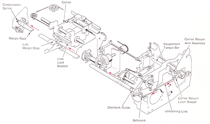
Figure 3 — Carrier Return Unlatching
TORQUE LIMITER
If the carrier is already resting at the left margin when a carrier return operation is selected, the carrier return mechanism must be allowed to slip in order to prevent parts breakage.
To do this, rotational motion of the operational shaft is supplied to the carrier return clutch arbor through a torque limiter (Figure 4). The torque limiter is a spring clutch which gives a controlled amount of torque to the carrier return clutch arbor.
The torque limiter consists of the torque limiter hub, which is attached to the operational shaft, and the torque limiter spring. The left end of the torque limiter spring is attached to the torque limiter hub by an adjustable clamp. The right half of the torque limiter spring fits over the large shoulder of the carrier return clutch arbor.
The operational shaft turns in the unwinding direction of the torque limiter spring. This expands the spring and allows it to slip. The spring is heavy, and smaller in diameter than the carrier return clutch arbor over which it fits. The friction between the arbor and the spring is not enough to drive the arbor in the unwinding direction of the spring during carrier return. The right end of the torque limiter spring has a loop formed to accept an extension spring.
The extension spring is connected between this loop and an eccentric stud on the torque limiter hub (Level 1). The extension spring increases the force required to unwind the torque limiter spring so that no slipping occurs during normal carrier return. The torque limiter spring slips when the carrier cannot move to the left. It also slips at the beginning of a carrier return operation to provide an even start.
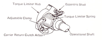
Figure 4 — Torque Limiter (Level 1)
The torque limiter extension spring on Level 2 machines is connected between the loop on the torque limiter spring and the extension lug on the torque limiter adjustable clamp (Figure 5).
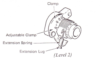
Figure 5 — Torque Limiter
CARRIER RETURN/PRINT INTERLOCK
The carrier return/print interlock is used to prevent the cycle clutch from releasing any time the carrier return mechanism is operated. A link is connected between the carrier return actuating arm and the character interrupter shaft. When the actuating arm is in the operated position. the character interrupter shaft is rotated to position the character interrupter pawl in the path of the cycle clutch link. This prevents the cycle clutch from releasing (Figure 6).
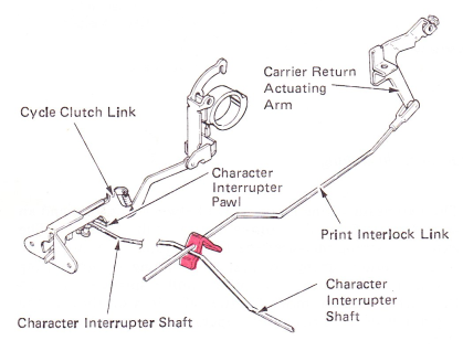
Figure 6 — CarrierReturn/Print Interlock