Selectric Resources
OPERATIONAL CONTROL ADJUSTMENTS
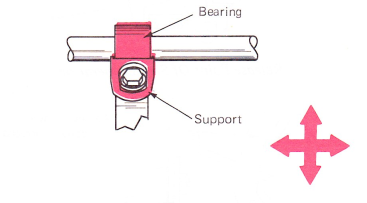
1. Operational Shaft Support — Adjust the operational shaft support front-to-rear to support the operational shaft with no binds.
NOTE: Bearing centered on support.
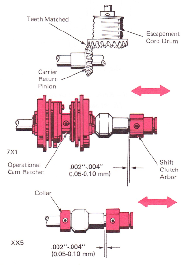
2. Operational Shaft Position And End Play — Position the operational shaft laterally so the teeth of the escapement cord drum and the carrier return pinion are even while maintaining .002”-.004” (0.05-0.10 mm) end play of the operational shaft. On the model 7X1, this adjustment is controlled by the operational cam ratchet and the shift clutch arbor. On longer machines, the position is controlled by a collar attached to the operational shaft and the shift clutch arbor.
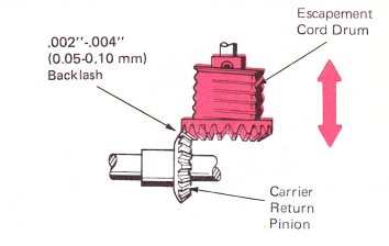
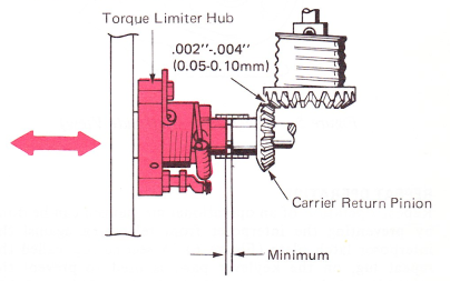
3. Carrier Return Pinion Backlash — Adjust the escapement cord drum gear front to rear to get .002”-.004” (0.05-0.10 mm) backlash between the carrier return pinion and the escapement cord drum gear while holding the escapement shaft to the rear.
NOTE: Recheck adjustment No. 1 after making this adjustment.
4. Carrier Return Pinion Side Play — Adjust the torque limiter hub left or right so there is minimum clearance with no binds between the carrier, the return pinion and the torque limiter arbor. There should be .002”-.004” (0.05-0.10 mm) backlash between the carrier return pinion and the escapement cord drum gear.
NOTE: Check with power on.
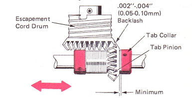
5. Tab Pinion Backlash — Adjust the tab governor assembly left or right to get .002”-.004” (0.05-0.10 mm) backlash between the tab pinion and the escapement cord drum gear, with the play in the escapement shaft removed to the rear. The pinion should have minimum end play between the tab governor hub and collar, yet still rotate freely.
NOTE: Check with power on.
6. Keylever Pawl Overlap — Adjust each keylever pawl guide so the keylever pawls overlap their interposers by .035”-.045” (0.89-1.14 mm) with both parts at rest. The index keylever pawl guide should be adjusted for .040”-.060” (1.02-1.52 mm) overlap. This overlap ensures proper repeat/nonrepeat operation.

7. Keylever Pawl T0 Interposer Clearance —
Levels 1 And 2 — Adjust the interposer latch plate for .030"-.035” (0.76-0.89 mm) between the index keylever pawl and interposer.

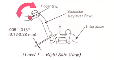
Level 1 — Adjust the spacebar keylever eccentric for a clearance of .005”-.015” (0.13-0.38 mm) between the keylever pawl and the interposer.
Level 2 — Adjust the spacebar keylever adjusting slot for .005”-.015” (0.13-0.38 mm) clearance between the keylever pawl and spacebar interposer.
Levels 1 And 2 — Adjust the keylever slots for a clearance of .020”-.030” (0.51-0.76 mm) between the backspace and carrier return keylever pawls and their interposers.

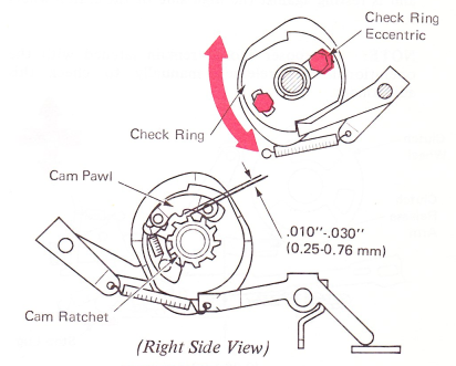
8. Operational Cam Check Ring — Adjust the operational cam check ring eccentric so that .010”-.030” (0.25-0.76 mm) exists between the tip of the cam pawl and the teeth of the operational cam ratchet with the cam latched in the rest position.
NOTE: Both the check ring mounting studs must be loosened before making this adjustment.
9. Operational Cam Position — Position the operational cam assembly left to right so that the clutch release arm for both the single- and double-sided cams has equal lateral position on the clutch wheel.
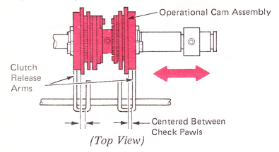
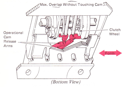
10. Release Arm Overlap — Form the operational cam release arms left-to-right to get the maximum amount of overlap on the clutch wheel as possible without touching the cam.
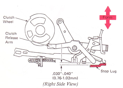
11. Clutch Release Arm Overlap — Form the adjustable stop lugs on the operational control bracket so each clutch release arm engages its clutch wheel by .030”-.040” (0.76-1.02mm). This adjustment may be observed by measuring the amount of clearance between the stop lugs and the lower extension of each clutch release arm when the release arm has released the clutch wheel and is resting against the high side of the clutch wheel tooth.
NOTE: Interposer should remain latched with the operational cam released manually to check this adjustment.
12. Clutch Release Arms — Form the lug at the bottom of each clutch release arm so it clears the operational interposer lugs by .030”-.040” (0.76-1.02 mm) with the operational interposers and operational cams at rest. This adjustment ensures the proper timing of the operational cam in relationship to the rest of the mechanism.

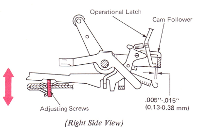
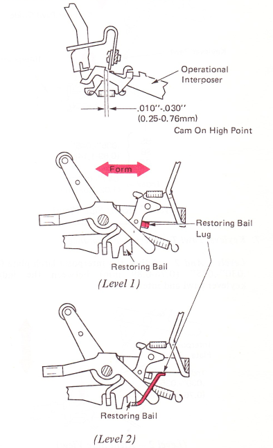
13. Interposer Restoring Bail — Form the lug at each side of the restoring bail so the interposers will be restored forward .010”-.030” (0.25-0.76 mm) past their latching point when either cam is operated. The lugs should be formed front-to-rear to get this adjustment. Forming the lugs forward increases the throw of the interposers. This adjustment ensures positive relatching of the interposers without excessive overthrow.
14. Interposer Adjusting Screws — Adjust the three interposer adjusting screws so a front-to-rear clearance of .005”-.015” (0.13-0.38 mm) exists between all the operational latches and their cam followers. Adjust the index interposer adjusting screw to match the approximate position of the other adjusting screws. This adjustment may be checked by operating the operational cams enough to move the cam followers down slightly at the rear. With the machine on its back, the latches can be pushed against the cam followers to estimate the clearance.
NOTE: On RB/S machines only, the spacebar interposer adjusting screw should be adjusted equal to the backspace screw.