Selectric Resources
SPACEBAR OPERATIONAL THEORY
The purpose of the spacebar mechanism is to provide a means of moving the carrier to the right one space at a time without printing. The spacebar is mounted at the front of the keyboard on a pivot shaft (Figure 1). Depressing the spacebar causes the pivot shaft to rotate and in turn rotates the spacebar keylever. As the spacebar is depressed, a lower lug of the keylever pawl contacts the operational interposer.
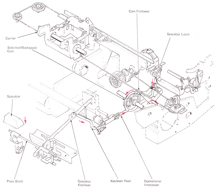
Figure 1 — Spacebar Mechanism
SPACEBAR OPERATION
Movement of the cam follower pulls the spacebar latch down, which causes the spacebar latch lever to pivot (Figure 2). An adjusting screw on the latch lever contacts the trigger lever, causing the trigger lever to rotate about the pivot pin. This causes the trigger on the trigger lever to rotate the escapement torque bar and allow the carrier to complete an escapement operation in the same way as a character print escapement.
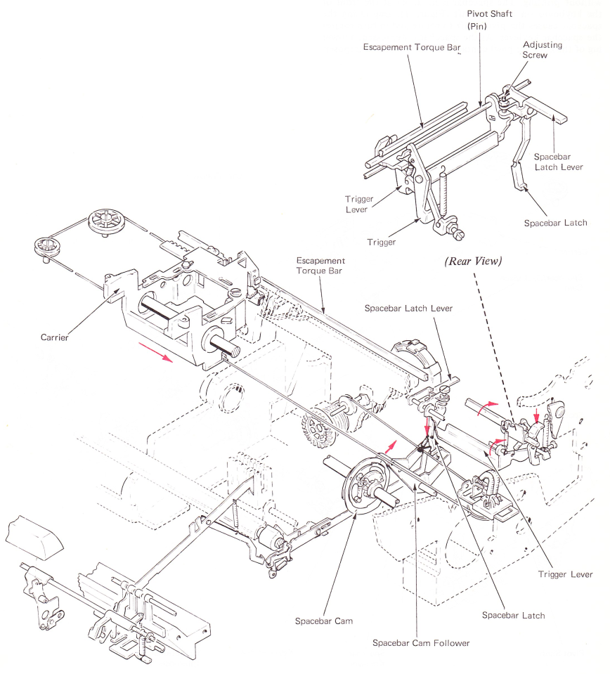
Figure 2 — Spacebar Operation
PRINT-TO-SPACE INTERLOCK
Both spacebar escapement and print escapement operate by actuating the escapement trigger lever to cause an escapement operation. Because of the relationship of these two mechanisms, operating both of them quickly or together causes only one space of escapement to occur. This could happen when an operator strikes the spacebar too soon after a character print operation.
To ensure the spacebar will cause an escapernent operation following a print cycle, it is necessary to place the spacebar mechanism into storage until the print cycle is completed (Figure 3).
Spacebar storage is done by blocking the movement of the spacebar interposer to the rear. As the filter shaft rotates during a print operation, the interlock interposer follows the side of the spacebar interlock cam and pivots top to the front. As the interlock interposer drops off of the high point of the cam, the rear extension moves up and blocks the movement of the spacebar interposer to the rear. This stops the spacebar operation and holds the interposer in storage until the print cycle is completed.
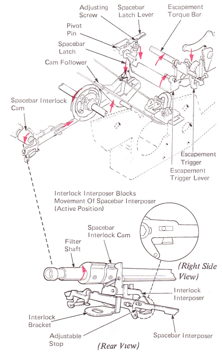
Figure 3 — Spacebar Operation & Print-To-Space Interlock
On level 1 machines, spacebar storage is done differently (Figure 4). A lockout cam is spring loaded toward the right against the escapement cam. In the rest position, the lockout cam is held to the left by the lateral working surfaces of the two cams. In this position, the spacebar interposer is free to operate without interference.
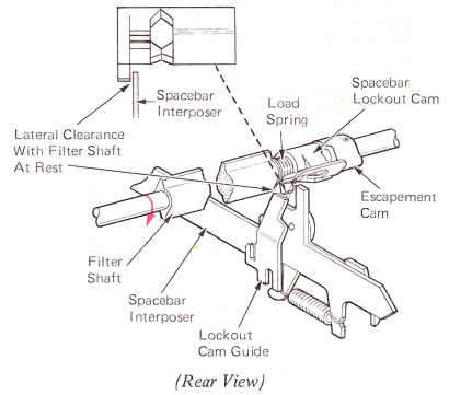
Figure 4 — Spacebar Interlock (Level 1 — At Rest)
During a character cycle, rotation of the filter shaft allows the lockout cam to move toward the right because the high points of the lateral working surfaces are no longer in contact (Figure 5). The lockout cam is prevented from rotating with the filter shaft by a guide bracket that fits in a slot in the front of the cam. As the lockout cam slides to the right, an extension at the bottom of the cam moves into the path of a lug on the spacebar interposer. As the filter shaft reaches its rest position, the lockout cam is forced back to the left by the escapement cam. The spacebar interposer is then released and normal spacebar operations can occur.
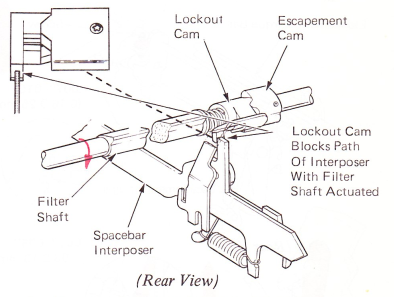
Figure 5 — Spacebar Interlock (Level 1 — Lockout Actuated)
The interlocks described above are called print-to-space interlocks. This is because the print cycles come before the spacebar cycles. This type of interlock is necessary in case the operator hits a spacebar cycle too soon after a character print cycle.