Selectric Resources
PAPER FEED AND INDEX ADJUSTMENTS
NOTE: The platen position must be correct before any paper feed adjustments are made. (See Print section.)
1. Paper Feed Support (Tie Rod Only) — With the feed roll tension spring disconnected, position the center support bracket so that the forward lug just touches the bottom of the feed roll actuating shaft while the rear lug just touches the top of the carriage tie rod. The center support bracket should not bend the copy control shaft.
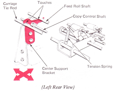
2. Feed Roll Tension (Tie Rod Only) — Place the feed roll tension springs in the hole of the feed roll arms that will provide proper tension measured at the front feed roll pivot points. The 7X1 machines should be adjusted for 48 oz.(1350 g) tension and the XX3-XX5 machines should be adjusted for 32-40 oz. (907-1134 g) tension.
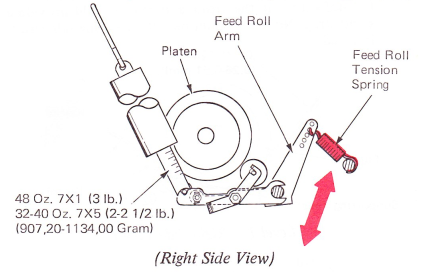
Feed Roll Tension (”A Frame”) — Place the feed roll tension springs in the notch that will provide 32-40 oz. (907-1134 g) tension when measured at the front feed roll pivots.

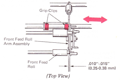
3. Feed Roll End Play (Tie Rod Only) — Adjust the feed roll assemblies for .010”-.015” (0.25-0.38 mm) side play of the feed rolls. Make this adjustment by moving the grip clips on the actuating shaft and moving the right front feed roll assembly on 7X1, and the left and right front feed roll assemblies on the XX5.
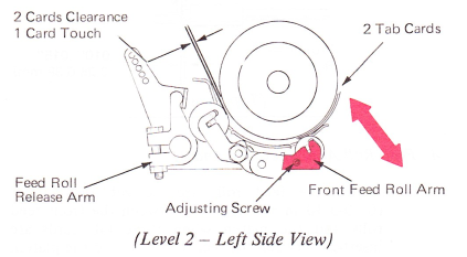
4. Feed Roll Arms (Levels 1 And 2) —
a. Adjust the feed roll arms to get .008”-.012” (0.20-0.30 mm) clearance between the front feed rolls and the platen when three tab cards are inserted between the rear feed rolls and the platen.
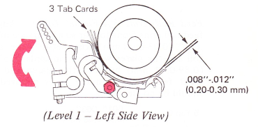
b. Adjust the front feed roll arms vertically to get a slight clearance between the rear feed rollers and the platen when two tab cards are between the front feed rollers and the platen. With one tab card between the front feed rollers and the platen, the rear feed rollers should have a slight drag on the platen.
An easy way to make this adjustment is as follows: Remove the paper deflector and insert three tab cards between the rear feed rollers and the platen. Loosen the adjusting screw. While pressing the front feed roll arm toward the platen, tighten the adjusting screw. Do the same for the opposite end. Then check for the above adjustment. The feed roll release arms must not limit the motion of the feed roll arms.
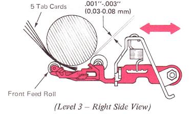
Feed Roll Arms (“A Frame” Only) — Adjust the feed roll arms front to rear so a clearance of .001 ”-.003” (0.03-0.08 mm) exists between the rear feed roll and the platen with five tab cards .035”-.037” (0.89-0.94 mm) between the platen and all the front feed rolls. With the cards removed, there should be no clearance.
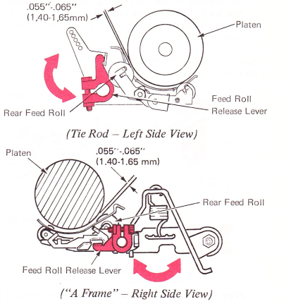
5. Paper Release — Adjust the feed roll release levers front to rear to get .055”-.065” (1.40-1.65 mm) clearance between the rear feed rollers and the platen when the feed rollers are released.
Excessive clearance can cause interference between the front feed roll and the carrier. Not enough clearance will not allow the feed rolls to release thick paper packs.
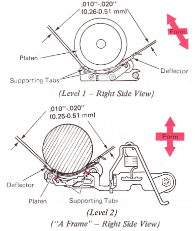
6. Deflector — Form the deflector supporting tabs on the front and rear feed roll arms to get clearance of .010”-.020” (0.25-0.51 mm) between the deflector and the platen. Three tab cards inserted between the platen and the deflector, at the front and rear, should provide a slight drag. No drag should be felt when one tab card is inserted.
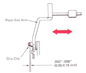
7. Paper Bail — Adjust the grip clip on the paper bail pivot shaft to get .002”-.006” (0.05-0.15 mm) end play of the paper bail arm. If necessary, form the bail shaft for equal bail roll contact with platen.
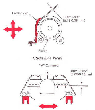
8. Cardholder — Adjust the cardholder brackets front-to-rear to get .005”-.015” (0.13-0.38 mm) clearance with the platen. The vertical adjustment should be such that the horizontal line is parallel and .002”-.005” (0.05-0.13 mm) below the feet of the typed characters when viewed from the operator’s position. Adjust the cardholder left to right so the point of the letter V will align with the vertical lines on the cardholder.
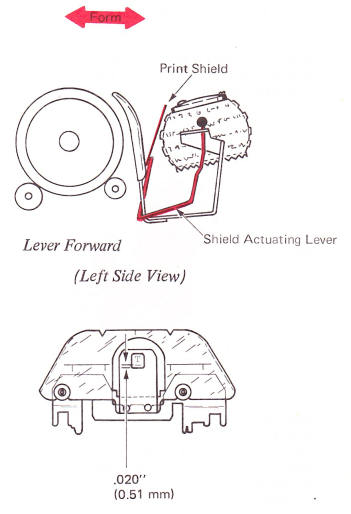
9. Removable Print Shield — If installed, form the shield actuating lever to satisfy the following conditions:
a. So the shield is against the platen when the lever is in the rear, latched position.
b. The print shield should rest against the element with the shield actuating lever in the forward or typing position. Fold the shield at the bottom, if necessary, to get this condition.
When the load lever of the film ribbon mechanism is activated, the shield will automatically be positioned to the rear. The ribbon must be installed between the shield and the typehead.
When the cardholder is adjusted for proper registration, the shield will be in the correct position. As an adjustment check, type an uppercase T, backspace and type an underscore. The T should be in the center and the underscore approximately .020" (0.51 mm) from the bottom of the hole.
NOTE: All operational control adjustments must be correct before making the following adjustments.
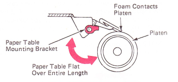
10. Paper Table Arm — Form the arms on the paper table to get minimum end play with no binds between the paper table arms and the paper table mounting bracket.
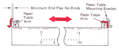
11. Paper Table Mounting Brackets — Adjust the paper table mounting brackets around their mounting screws so the foam on the paper table will contact the platen and the paper table is flat over its whole length.
NOTE: The operational shaft must be adjusted correctly before making the following index adjustments.
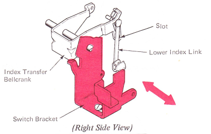
12. Switch Bracket (RB/S) — Adjust the switch bracket left or right to ensure that the lower index link does not bind in the slot in the index transfer bellcrank.
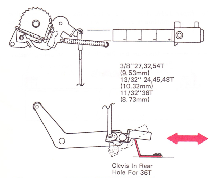
13. Multiplying Lever Stop — Adjust the multiplying lever stop front to rear to produce 3/8” (9.53 mm) (27, 32, 54T); 13/32” (10.32 mm) (24, 45, 48T); 11/32” (8.73 mm) (36T) motion to the index link when the carrier return index cam is operated to its high point (platen removed).
NOTE: The clevis should be in the rear hole of the multiplying lever for 36 tooth mechanisms.
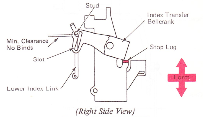
14. Index Transfer Bellcrank Stop Lug (RB/S Only) — Form the index transfer bellcrank stop lug to get a minimum end play, no bind condition between the stud on the lower index link and the lower horizontal edge of the slot in the index transfer bellcrank. This will ensure that the lower index link stud restores to the front of the slot after a backspace operation.
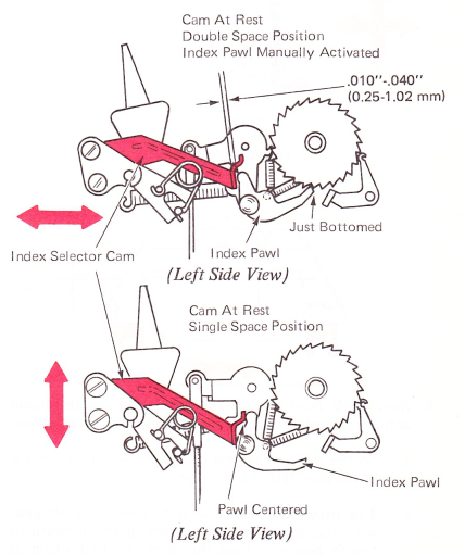
15. Index Selector Cam — 27-Tooth Ratchet — Adjust the index selector cam so a clearance of .010”-.040” (0.25-1.02 mm) can be observed between the working surface of the selector cam and the rear tip of the index pawl. To make this adjustment, place the index lever in the double-space position, press down on the index link until the index pawl is just bottomed in a ratchet tooth, and adjust the selector cam.
With the index lever in the single-space position, adjust the selector cam vertically so the index pawl is centered on the cam surface.
These adjustments must be considered together and readjusted until both are correct.
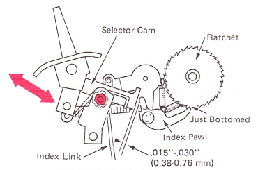
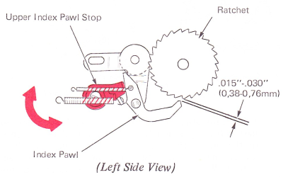
Index Selector Cam — 54-Tooth Ratchet — With the index lever in the 1-1/2 linespace position, press down on the index link until the index pawl is just bottomed in a ratchet tooth. Adjust the index selector cam so a clearance of .005”-.030” (0.13-0.76 mm) can be observed between the working surface of the selector cam and the rear tip of the index pawl.
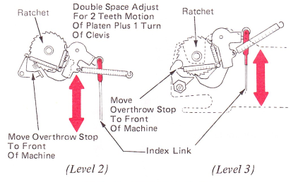
16. Index Link — As a preliminary step, loosen the platen overthrow stop and move it to the front of the machine. With the platen installed and the feed rolls engaged, hold the detent roller disengaged from the platen ratchet. Manually cycle a double line space operation. At the end of the cycle, allow the detent roller to enter the platen ratchet. Adjust the index link so the detent roller will bottom between the two ratchet teeth without causing any rotational movement of the platen. Adjust the index link clevis to get this condition, then shorten the link one turn to get .015”-.020” (0.38-0.51 mm).
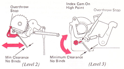
17. Platen Overthrow Stop — Adjust the platen overthrow stop front to rear to get minimum clearance with no binds between the index pawl and the platen overthrow stop with the index cam rotated to its high point.
NOTE: The following adjustments are for early level machines only.
18. Index Link And Index Stud (Level 1) — As a preliminary setting, position the index link stud in the center of the slot in the pawl carrier. The following adjustments may require that the position be changed slightly. With the index selection lever in the single line space position and the carrier return/index cam latched at rest, insert four tab cards between the carrier return
cam and the cam follower. Adjust the index link so the index pawl is bottomed in the ratchet against the tooth.
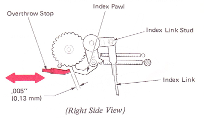
With the carrier return index cam on the high point, adjust the index stud front to rear to get one full tooth of motion from the index pawl after it starts to drive the platen. The upper index pawl stop must allow the index pawl to bottom in the ratchet.
NOTE: Adjustment of the index link and index link stud must be considered together. Adjust and check each one until both are correct.

19. Upper Index Pawl Stop (Level I) — With the index cam latched at rest, adjust the upper index pawl stop to get .015”-.030” (0.38-0.76 mm) clearance between the index pawl and the platen ratchet.
20. Multiplying Control Lever (Level 1) — Position the multiplying control lever stop front to rear so the elongated hole is centered on its mounting stud. This is a preliminary adjustment and may need to be changed slightly.
Adjust the multiplying control lever vertically to just clear the bottom edge of the multiplying lever with the carrier return index cam at rest. Keep the high point of the eccentric toward the front of the machine.
Adjust the multiplying control lever stop front to rear to get two full teeth of motion from the index pawl after it begins to drive the platen. Be sure that the index motion is not limited by the platen overthrow stop.

21. Platen Overthrow Stop (Level 1) — Adjust the platen overthrow stop front to rear to get a clearance of .005” (0.13 mm) between the index pawl and the platen overthrow stop with the index cam rotated to its high point.
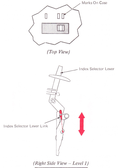
22. Index Selector Lever — Adjust the index selection lever link so that the index selection lever aligns with the double mark on the case when the lever is in double space position.
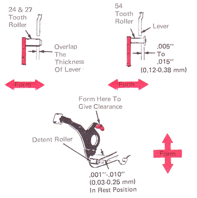
23. Line Position Reset Lever “Selectric” Typewriter — Form the right-hand extension of the line position reset lever to get .001”-.010” (0.03-0.25 mm) clearance between the detent roller and the lever with the lever at rest. Form the detent arm so the lever overlaps the detent roller by the thickness of the lever. Machines equipped with a 54-tooth detent arm should have .005”-.015” (0.13-0.38 mm) between the lever and the “C” clip.
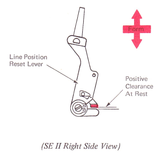
Line Position Reset Lever “Selectric” II Typewriter — Form the rear extension of the detent arm to clear the lower lug of the line position reset lever.
24. Left Platen Knob — Position the knob left or right to get .158”-.218” (4.02-5.54 mm) clearance between the left-hand platen bushing and the platen knob.

25. Right Platen Knob — Position the knob left or right to get minimum end play and no binds between the right-hand platen bushing and the knob. The bushing should turn freely.
