Selectric Resources
PAPER FEED AND INDEX OPERATIONAL THEORY
The purpose of the paper feed and index mechanism is to hold the paper against the platen so that it will move with the platen as it is indexed vertically.
The paper feed mechanism uses an “A frame” for support and contains all the parts necessary to control paper feed.
The paper is held against the platen by the front and rear feed roll assemblies located below the platen. Each feed roll assembly contains three or four rubber rollers equally spaced across the feed roll shaft and attached to the shaft.
The feed rolls mount in the front and rear feed roll arm assemblies. Each feed roll arm assembly turns on a pivot stud at the rear of the “A frame.” Heavy extension springs, connected between the “A frame” and feed roll arm assemblies, supply constant tension on the feed rolls. There are several notches cut into the feed roll arm assemblies to provide a means of adjusting the feed roll pressure.
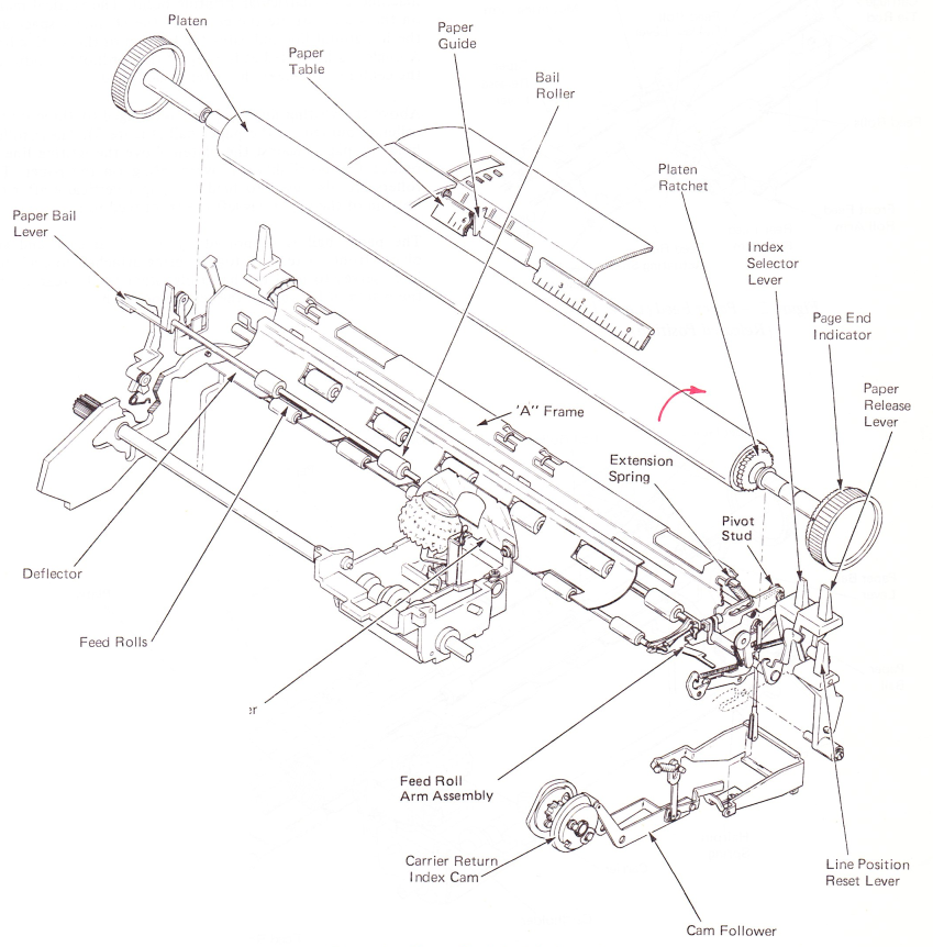
Figure 1 — Paper Feed And Index
LEVEL 1 PAPER FEED
On level 1 paper feed assemblies, a carriage tie rod supports the paper feed mechanism. The paper feed mounting arms attached to the carriage tie rod support the feed roll arm assemblies and the feed roll actuating shaft. The feed rolls mount in the front and rear feed roll arm assemblies. The front feed roll arms pivot on the feed roll actuating shaft. Also pivoting on the feed roll actuating shaft is a feed roll tension arm. Heavy extension springs are connected between the carriage tie rod and one of the holes in the feed roll tension arm to provide a means of adjusting the feed roll pressure (Figure 2).
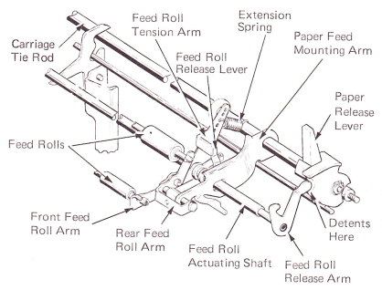
Figure 2 — Paper Feed (Level 1) (Released Position)
PAPER FEED
As the paper is inserted into the machine, an adjustable paper guide, mounted on the center cover at the rear of the platen, serves to position the paper for its left margin position (Figure 3). The paper deflector guides the paper between the rear feed roll and the platen. As the platen is turned, the paper is forced to move with the platen. The deflector guides the paper around the platen into position between the front feed roll and the platen. As the paper is fed further, the end of the paper is guided up by the cardholder attached to the rear of the carrier.
The cardholder helps to hold the typing material against the platen in the printing area. A scale on each side of the cardholder aids the typist in inserting material into the machine to a particular printing point. The vertical marks on the scale indicate the center of the character space and the horizontal line indicates the bottom of the writing line. A single mark, located at the top of the cardholder, indicates the center of the next character to be typed.
Above the writing line the paper is engaged by three rubber rollers mounted on the paper bail (Figure 3). These rollers hold the paper against the platen above the writing line to reduce the possibility of overprinting on the paper. The rollers are also used to feed the paper vertically after the bottom of the paper has left the front feed rolls.
The paper bail is supported by a lever at each end and pivots front to rear. A toggle spring attached to each bail lever serves to hold the bail rolls either to the rear against the platen or forward in the release position.
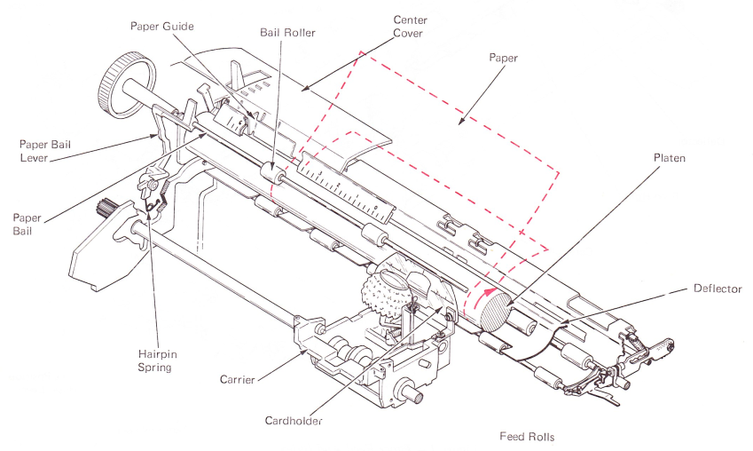
Figure 3 — Paper Feed
PAPER RELEASE
The pressure of the feed rolls can be released from the platen by pulling forward on the paper release lever located at the right end of the machine. This will allow the operator to position the paper correctly and make it easier to insert and remove the paper (Figure 4). The front of the paper release lever cams the feed roll actuating shaft and has a lug resting on each feed roll tension arm. As the shaft rotates, the feed roll release levers rotate the feed roll tension arms, moving the feed rolls away from the platen. When the paper release lever has been pulled all the way forward, the end of the feed roll release arm moves into a detent that holds the feed roll release lever in the released position.
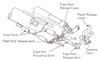
Figure 4 — Paper Release Mechanism (ReleasedPosition)
Paper release on machines equipped with tie rod support is done by pulling forward on the paper release lever located at the right end of the machine (Figure 5). A cam surface on the front of the paper release lever cams the feed roll release arm forward to rotate the feed roll actuating shaft. The feed roll release levers are clamped to the feed roll actuating shaft and rest behind a lug on each feed roll tension arm. As the shaft rotates, the feed roll release levers rotate the feed roll tension arms and the front feed roll arms down, away from the platen. Due to the connection between the front feed roll arm and the rear feed roll arm, the rear feed roll arms are forced away from the platen. When the paper release lever has been pulled all the way forward, the end of the feed roll release arm moves into a detent to hold the feed roll release lever in the released position.
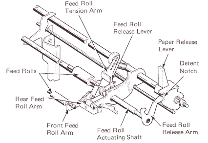
Figure 5 — Paper Release (Released Position)
INDEX MECHANISM
The index mechanism linespaces the paper vertically. An index operation can be done by depressing either the carrier return keylever or the index keylever. Depressing the carrier return keylever also causes the carrier to move to the left margin. Depressing the index keylever causes only an index operation. The index selector lever may be positioned so the mechanism will line space either one or two lines during each operation. With the lever in the forward position, single line spacing will occur. The mechanism will double line space if the lever is to the rear. Indexing is done by a pawl which engages and rotates a ratchet on the right end of the platen (Figure 6). The ratchet is locked to the platen so the platen will rotate.
Motion to operate the index mechanism is supplied through the carrier return/index cam. Motion is then transferred through the cam follower to the multiplying lever and the index link. The rear of the multiplying lever is always in contact with the multiplying lever stop which is attached to the power frame. The index link will receive the same amount of motion each time the cam operates, for each position of the index selector lever.
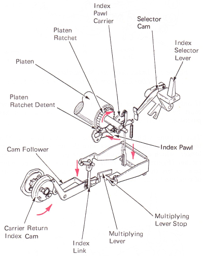
Figure 6 — Index Operation
INDEX SELECTION MECHANISM (EXCEPT 54 TOOTH)
The index pawl entry into the platen ratchet is controlled by the selector cam located on the index lever (Figure 7). The selector cam has two steps at the forward end, in a position to contact the rear of the index pawl. The index pawl is spring loaded toward the ratchet.
The selector cam is held in the single or double space position by a toggle spring. The selector cam movement is limited by two extensions at the bottom of the lever that contact the toggle spring mounting stud.
In the double line space position, the index pawl is allowed to enter the platen ratchet immediately. The index pawl then rotates the ratchet two spaces until the pawl contacts the platen overthrow stop. The platen overthrow stop holds the pawl into the ratchet tooth to prevent further rotation of the platen. The platen detent roller is spring loaded into the ratchet teeth. During an index operation, the platen detent roller is moved into the next tooth of the platen ratchet to maintain platen position.
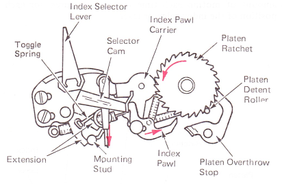
Figure 7 — Index Selection Mechanism (Double Space Position — Left Side View)
If only a single space operation is desired, the index pawl must be prevented from entering the ratchet until it has passed one tooth of the ratchet.
This is done with the index selector lever forward. The index pawl maintains contact with the line space cam lever longer, which delays the entry of the pawl into the platen ratchet (Figure 8). The remaining motion after the index pawl enters the ratchet is enough to cause only one tooth of rotation to the platen.
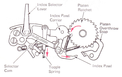
Figure 8 — Index Selection Mechanism (Single Space Position — Left Side View)
PAWL OPERATION
The index pawl has an elongated pivot hole so that it moves forward during part of the index stroke (Figure 9). As the index mechanism operates, the pawl engages the ratchet tooth. There is a slight delay until the pawl carrier reaches the end of the elongated slot in the index pawl. Because of the speed at which the pawl carrier operates, the platen is caused to move before the index stroke. Without the elongated hole in the index pawl, the platen ratchet would reach the final position before the index pawl. This is prevented by the pawl moving with it and reaching the overthrow stop at the same time the platen reaches the final position. The pawl is then held into the ratchet and blocks any further rotation of the platen.
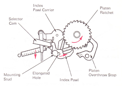
Figure 9 — Index Pawl Operation (Left Side View) (Double Space Position)
54-TOOTH INDEX SELECTION MECHANISM
The 54-tooth index mechanism operates basically the same as the mechanism just described. However, there are three positions for the index lever (Figure 10). The selector cam has an elongated hole with three detent positions on the lower side. An adjustable stud mounted on the index bracket moves into one of the detents of the selector cam to control index pawl entry into the platen ratchet. This controls feeding two, three or four ratchet teeth to index the platen a space, space and a half, and two spaces.
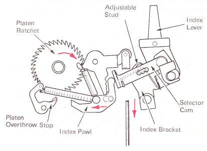
Figure 10 — Half Line Spacing(Right Side View)(One And A HalfSpace Position)
PLATEN VARIABLE
The platen variable is used for typing permanently above or below the writing line or locating the writing line after inserting the paper (Figure 11). The platen ratchet must remain stopped when selecting a new writing line so that the detent roller will be bottomed between the two teeth of the ratchet at the new position. A clutch mechanism connects the ratchet to the platen so that it can be engaged for line spacing and disengaged by pushing the left-hand platen knob toward the right. As long as the platen knob is held to the right, the platen can be rotated freely while the ratchet remains stopped. When the knob is released, the clutch is automatically re-engaged by spring tension.
When the driver is disengaged from the platen end plug, the platen can be turned to the desired position. The driver can then engage different grooves and lock the platen in the new position. The left-hand platen knob is mounted to a shaft that slides left to right inside the platen. A light compression spring holds the shaft toward the right to prevent free play. The shaft pushes against the platen driver. Movement of the platen knob toward the right is transferred to the driver to disengage it from the platen end plug.
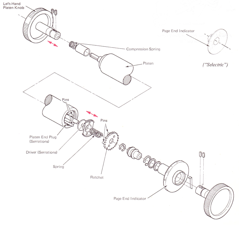
Figure 11 — Platen Variable And Page End Indicator
The left side of the platen ratchet contains two pins that fit into holes in the platen driver. The platen driver operates left to right and always turns with the ratchet. A compression spring between the ratchet and the driver loads the driver to the left so the grooves on the outer surface of the driver engage with matching grooves inside the platen end plug. The engaging of the grooves causes the platen, the driver and the ratchet to be locked together and turn as a unit.
PAGE-END INDICATOR
The page-end indicator (Figure 11), located on the inside of the right-hand platen knob, allows the operator to know calibrated in half inches. The operator must align the top edge of the paper with the writing line on the cardholder. For a standard size sheet of paper, the operator must rotate the indicator until position 2 is in line with the horizontal mark on the top of the typewriter next to the right platen knob. When using other than standard 11” paper, the operator may locate the indicator setting from the page-end indicator chart in the operator manual.
Figure 11 — Platen Variable And Page End Indicator
LINE POSITION RESET LEVER
The line position reset lever mechanism (Figure 12), located on the right end of the platen, allows the operator to leave a typed line, and return again. When the lever is moved forward, the ratchet detent is moved away from engagement with the platen ratchet. The platen is then free to turn without contacting the detent. After the operator has made the insertion or correction, the platen must be returned to the approximate typing line, and the lever to its home position. This relocates the typing line by allowing the ratchet detent to engage the platen ratchet.
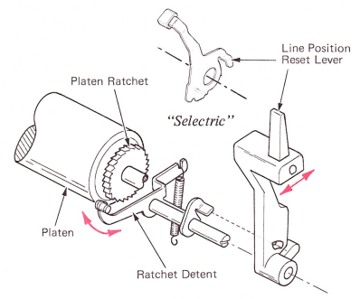
Figure 12 — Line Position Reset Lever