Selectric Resources
FILM RIBBON OPERATIONAL THEORY
The purpose of the film ribbon mechanism is to lift the ribbon into the path of the typehead during a print operation and to feed the ribbon from the supply spool to the take-up spool.
The film ribbon mechanism mounts on and moves with the carrier assembly. The supply spool of ribbon mounts on a permanent supply spool on the left side of the carrier. Due to the inner-connection between the plastic core of the supply spool and the permanent supply spool, both spools rotate as a unit during a ribbon feed operation. As the ribbon comes from the supply spool, it threads around the ribbon circuit to the take-up spool. The take-up spool is a throw away, clear spool mounted on the right side of the carrier. After the ribbon has been used and fed to the takeup spool, both the take-up spool and the plastic core from the supply side are removed and thrown away. The new ribbon to be installed comes equipped with its own take-up spool attached to the end of a clean leader (Figure l).
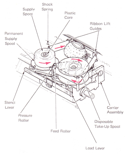
Figure 1 — Film Ribbon Mechanism
RIBBON FEED
The ribbon feed cam, which is keyed to the print sleeve, supplies the motion for ribbon feed. The motion from the cam is transmitted through an adjustable stud to the cam follower, which drives the feed pawl (Figure 2). The cam follower mounts on a bracket that is attached to the front carrier casting by two hex-head screws. An extension spring connects to one of these screws and loads the cam follower against the cam. The feed pawl mounts at the top of the cam follower by a shouldered rivet and is spring loaded into engagement with the ribbon feed and lift wheel.
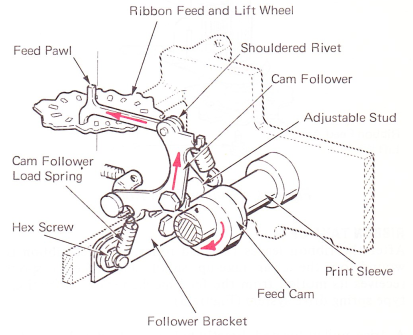
Figure 2 — Ribbon Feed Mechanism (Half Cycle Position)
The ribbon feed and lift wheel contains sixteen feed windows (Figure 3). During the first half of a print cycle, the cam follower will go to the low point of the feed cam under spring tension. The feed pawl attached to the top of the cam follower will move to the rear, out of one window and into the next. As the feed cam follower and feed pawl are powered forward, the feed and lift wheel will be rotated clockwise. The wheel will rotate one window during each print cycle.
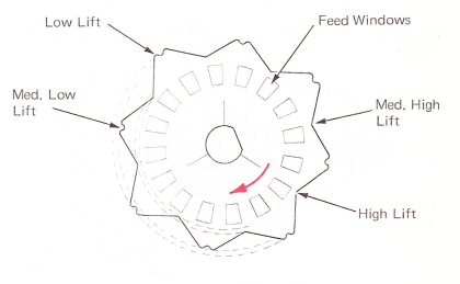
Figure 3 — Ribbon Feed & Lift Wheel (Top View)
A ribbon feed roller is mounted to the top of the feed and lift wheel and is held by a left-hand threaded screw (Figure 4). The feed roller rotates clockwise each time the feed and lift wheel is rotated. The used ribbon passes around the feed roller just before winding on the take-up spool. A pressure roller holds the ribbon against the feed roller so that the amount of rotation of the feed roller will determine how much ribbon is fed on each cycle.
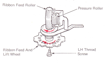
Figure 4 — Ribbon Feed Roller
RIBBON TAKE-UP
After the ribbon leaves the feed roller, the used ribbon is wound on the clear take-up spool. The take-up spool receives its motion from the feed mechanism by a friction type spring drive system (Figure 5).
A drive pulley located directly below the feed roller rotates with the feed roller during a ribbon feed operation. This drive pulley supplies the motion to the take-up pulley through a drive spring. The take-up pulley, driven by the drive spring, rotates about the take-up spool pivot stud and is held in place by a “C” clip. The shape of the groove in the take-up pulley is designed slightly different from that of the drive pulley. This is to allow all of the necessary slippage of the drive spring to occur at the take-up pulley and not at the drive pulley. This slippage is necessary to ensure the take-up spool will wind all of the ribbon. Two hooked lugs on the top face of the take-up pulley fit into slots in the bottom of the clear take-up spool. These lugs provide a locking connection between the take-up pulley and the take-up spool.
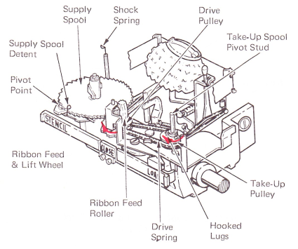
Figure 5 — Take-Up Spool Drive
To maintain a reliable ribbon tracking characteristic from the supply spool to the feed and pressure rollers, the ribbon must be kept slightly tight through the ribbon path. Any slack in the system will affect the tracking of the ribbon. The ribbon is kept tight by means of a shock spring and detent. As the ribbon is pulled through'by the feed roller, the supply spool detent, located on the front of the shock spring, releases the supply spool to allow the ribbon to feed (Figure 6).
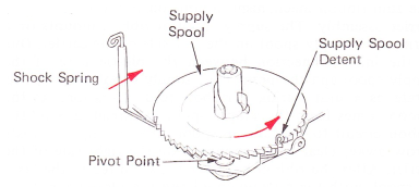
Figure 6 — Shock Spring And Detent
RIBBON LIFT
To get the desired number of characters per spool of ribbon, a 9/16” (14.3 mm) wide ribbon is used. By changing the ribbon lift position for each character, a greater number of characters can be typed on a given length of ribbon.
The ribbon lift mechanism consists of a ribbon lift cam, a cam follower, a control mechanism, and the ribbon lift guide assembly. The lift mechanism is mounted to the carrier and moves with it. The ribbon lift cam is a single side cam that is attached by setscrews to the left-hand side of the print sleeve. Each time a print cycle occurs, the cam makes one complete revolution (Figure 7).
The ribbon lift cam follower pivots on the carrier assembly above and to the rear of the cam. Each revolution of the cam raises the cam follower. The end of the ribbon lift control link fits into an elongated slot in the cam follower. The ribbon lift guide rests on the control link and pivots at the front of the carrier casting. As the cam follower is raised, the control link forces the ribbon lift guide assembly to pivot at the front and riase the rear of the assembly. A flat link from each side of the ribbon lift guide attaches to two pins at the front of the carrier to maintain the ribbon lift guide in a vertical position (Figure 7).
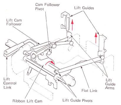
Figure 7 — Ribbon Lift Mechanism
The four lift positions set by moving the control link are indicated by “A,” “B,” “C” and “D” (Figure 8A).
Positions “A” and “C” are low lift positions while “B” and “D” are high lift positions. These four lift positions occur in a particular order during a typing operation. It takes four print operations to complete a lift cycle, which is from “A” to “B” to “C” to “D.” On the fifth print operation, the lift cycle begins all over again with lift position “A.” Changing the location of the lift control link in the slot of the cam follower produces these lift positions.
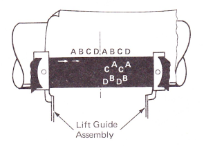
Figure 8A — Typed Sample
Each of these cam surfaces aligns with one of the feed windows to produce the four lift positions as the wheel rotates for each ribbon feed operation (Figures 8B and 8C).
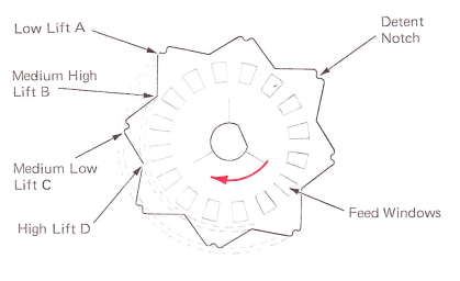
Figure 8B — Ribbon Feed And Lift Wheel (Top View)
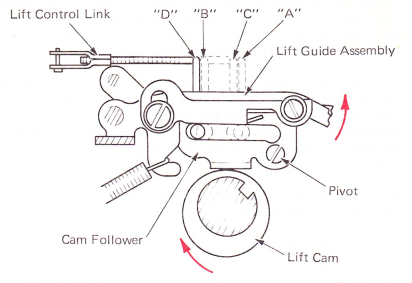
Figure 8C — Ribbon Lift Positions (Right Side View)
The motion produced by the cam surfaces on the ribbon feed and lift wheel is transmitted to the lift control link by the ribbon lift control lever. The lift control lever is mounted to the front of the carrier by a shouldered screw and is spring loaded against the cam sides of the feed and lift wheel. During the early part of a print cycle, the feed and lift wheel rotates counterclockwise with the feed pawl. This happens because the feed pawl is pulled out of the feed window as it moves toward the rear of the machine. To prevent the feed and lift wheel from rotating counterclockwise, the ribbon lift control lever serves to detent the feed and lift wheel. This is done by a detent notch cut on the high sides of the ribbon feed and lift wheel (Figure 9).
The selected ribbon lift position for each print operation is always established by the ribbon feed operation from the previous print cycle. This is because the rotation of the feed and lift wheel does not occur until after the typehead has printed.
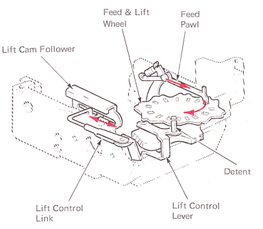
Figure 9 — Lift Control Lever
STENCIL CONTROL
When the machine is used for typing stencils, the ribbon feed and lift operation must be locked out. This is done by pushing the stencil lever, located on the front on the carrier, to the rear (Figure 10).
The lockout of the feed mechanism is done through a lug on the stencil lever. In the stencil position, the lug pivots to the right into the path of the vertical lug of the feed pawl. Ribbon feed is interrupted because the feed pawl is not allowed to move to the rear and drop into the next feed window.
Lockout of the lift operation is done by a cam surface on the left end of the stencil lever. As the lever is pushed into the stencil position, the lift control is moved away from the feed and lift wheel. This causes the control link to move to the rear of the slot in the cam follower where no lift motion will be produced to the ribbon lift guide assembly. The stencil lever must be pulled forward to restore ribbon feed and lift.
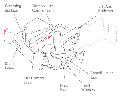
Figure 10 — Stencil Lockout
RIBBON LOAD
When the operator desires to change the ribbon, the load lever is pushed to the rear into its load position. This causes the ribbon lift guide assembly to rise above the typehead so the ribbon may be easily inserted through the guides. Latching the load lever in its load position causes the lower extension of the load lever to contact an extension on the lift guide assembly and push it upward. At the same time, an extension on the pressure roller lever is contacted by the upper part of the load lever and pivots the pressure roller away from the feed roller. The operator may now install a ribbon with nothing in the way (Figure 11).
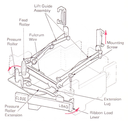
Figure 11 — Ribbon Load Position
NOTE: Lower extension of right-hand ribbon plate mounting screw is used to lock load lever latched in load position.
The level 1 film ribbon mechanism differs slightly from the mechanism just described. A supply drag lever is in contact with the ribbon supply spool (Figure 12).
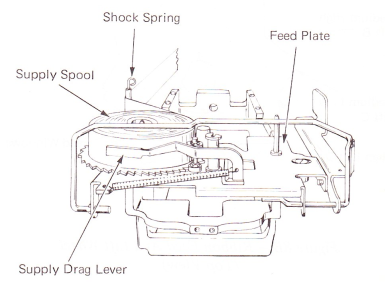
Figure 12 — Supply Drag (Level 1)
RIBBON FEED
During a feed operation, the supply spool brake is mechanically disengaged by the ribbon lift mechanism (Figure 13). The upper extension of the lift guide plate contacts the brake actuating lever when the lift guide is in the raised position. As the brake actuating lever pivots about its pivot point, it pushes the supply spool brake out of engagement with the supply spool.
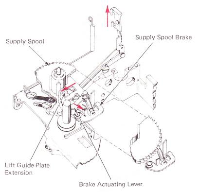
Figure 13 — Ribbon Shock Spring And Brake Actuating Lever (Level 1)
To prevent the ribbon feed and lift wheel from rotating backward during a feed operation, a detent spring falls into the feed windows of the ribbon feed and lift wheel (Figure 14).
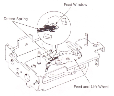
Figure 14 — Feed & Lift Wheel Detent Spring (Level 1)
STENCIL LOCKOUT
In the stencil position, the feed pawl shield is rotated under the feed pawl to prevent the feed pawl from operating in the feed windows (Figure 15). Lockout of the lift mechanism is done in the same way as the present mechanism. However, the parts design is slightly different.
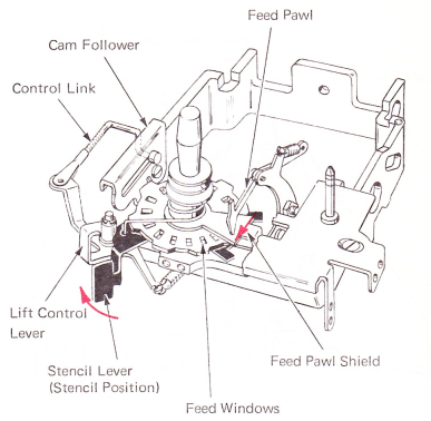
Figure 15 — Stencil Lockout (Level 1)
RIBBON LOAD
The ribbon load operation is started by a ribbon load bail (Figure 16). A link is connected between the ribbon load bail and the load lever. The load lever raises the lift guide assembly in the same way as the current load lever.
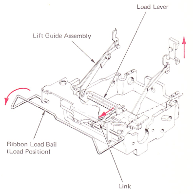
Figure 16 — Ribbon Load Operation (Level 1)
An adjustable pressure roller release arm is attached to the load lever to release the pressure roller in the load position (Figure 17). The pressure roller release arm pushes against the pressure roller lever. As the pressure roller lever pivots away from the feed roller, it also pushes the supply drag lever away from the supply spool. All interference is removed to allow the operator to install a new ribbon.
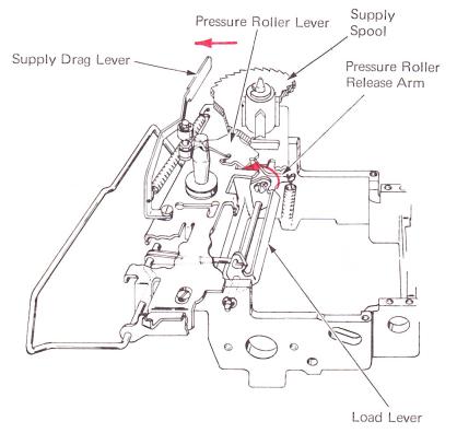
Figure 17 — Pressure Roller Release (Level 1) (Right Side View)