Selectric Resources
PRINT OPERATIONAL THEORY
The purpose of the print mechanism is to cause the typehead to strike the paper after a character is selected. When the printer is cycled for a character selection/print operation, motion is transferred by the print shaft through the print cam, a cam follower and the rocker assembly to power the typehead toward the platen (Figure 1).
There are two basic conditions necessary for a correct print operation. They are: correct velocity of the typehead as it strikes the paper, and proper platen position.
Two levels of velocity may be selected on machines having the dual velocity feature. Alphanumeric characters receive the highest velocity while smaller characters, such as punctuation and symbols, receive a lower velocity.
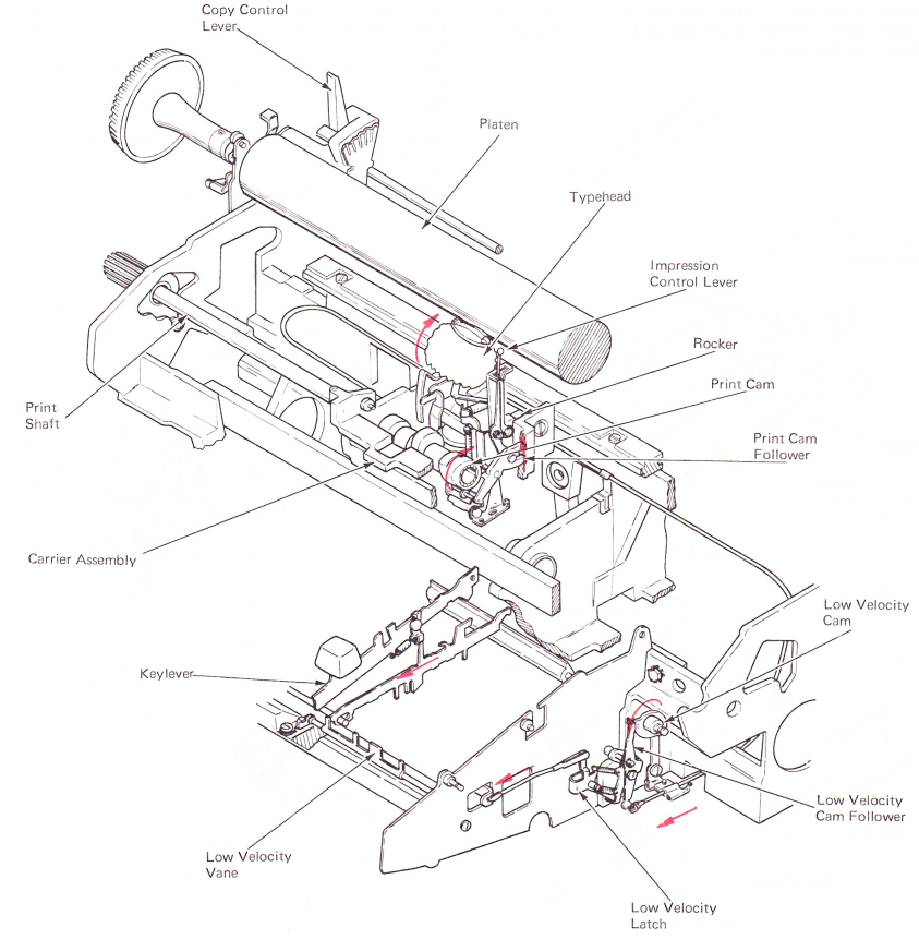
Figure 1 — Print Mechanism
FRONT CARRIER SUPPORT
The typehead is supported in front of the paper by a frame called the carrier (Figure 2). The carrier transports the typehead and related mechanism across the writing line. The carrier assembly is supported in front by the print shaft and a print sleeve. The print sleeve is keyed to the print shaft and turns when the print shaft is rotated. Motion for a print operation is taken off the print sleeve.
Due to up and down motion of the print shaft, the front of the carrier needs additional support. A support is located under the front of the carrier (Figure 2). On level 2 (XX3 and XX5) machines, a carrier pad contacts this anvil when motion of the print shaft occurs. On level 1 machines, a buffer screw and a buffer plate serve the same function. (Rear carrier support is covered in the Fine Alignment Section of this manual.)
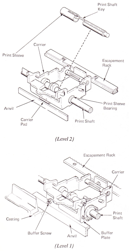
Figure 2 — Front Carrier Support
PRINT OPERATION
The print shaft supplies the drive to. operate the print cam mechanism (Figure 3). The print shaft extends the width of the frame and is supported in a bearing at each end. A gear at the left end of the print shaft engages an idler gear of the character selection mechanism.When the character selection mechanism is cycled, motion is transferred through the idler gear and the print shaft gear to rotate the print shaft top to rear. The print shaft is rotated 360 degrees each cycle.
The print cam is attached to the print sleeve, which in turn is keyed to the print shaft.
When the print shaft is rotated, motion is transferred through the print sleeve to rotate the print cam. Print cam motion is then transferred through the cam follower and the impression control lever to pivot the rocker assembly about the rocker shaft, and power the typehead toward the platen.
On level 2 print mechanisms, the print cam follower roller may be positioned opposite either side of the print cam. On machines without dual velocity, the print cam follower roller will always be positioned opposite the high velocity side.
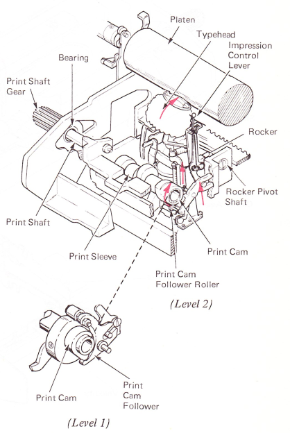
Figure 3 — Print Operation
IMPRESSION CONTROL LEVER (LEVEL 2)
The impression made by the typehead is determined by the velocity of the typehead upon impact with the paper. By increasing or decreasing the velocity of the typehead with the impression control lever, the impression for all characters can be changed equally.
The impression control lever may be positioned by the operator to one of five different impression settings (Figure 4). Changing the position of the impression control lever causes a pin in the lower part of the lever to move to the front or to the rear of the print cam follower arm. The front-to-rear position of the pin determines the amount of powered travel the typehead receives from the print cam follower. This, plus the amount of free flight, determines the velocity of the typehead upon impact with the paper.
Powered flight is the distance the typehead is driven toward the platen by the print cam. The remaining distance is called free flight. Free flight is the amount of typehead movement from the high point of the print cam to the platen.
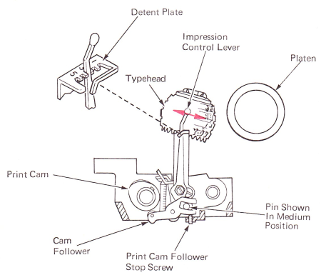
Figure 4 — Impression Control Lever (Level2) (Right Side View)
PRINT MECHANISM (LEVEL 1)
Level 1 machines did not have the automatic velocity control mechanism.The impression was a preset adjustment and could not be changed by the operator (Figure 5).
The print cam is a double cam. Its function is to power the typehead toward the platen and restore it to rest. A small cam surface on the right is the print cam and moves the typehead toward the platen. A larger cam surface on the left is called the restoring cam. It restores the typehead to rest and prevents rocker bounce.
The cam surface of the print cam is designed so the typehead is powered within a few thousandths of an inch of the platen. Because the typehead is powered nearly all the way to the platen, all the characters are forced to strike the paper slightly, even those with a larger surface area. This arm limits the amount of free flight of the typehead to provide an equal print force for all characters. A heavy arm called the anvil striker is attached to the bottom of the carrier and serves as a stop for the rocker. An anvil is located just under the front of the carrier, and extends between the side frames. It is an angle-shaped bar with an extension to the rear. As the typehead strikes the paper with the correct impression, the striker hits the bottom of the anvil and prevents further movement of the rocker and typehead. This means that the impression for each character will be consistent, with little change between characters.
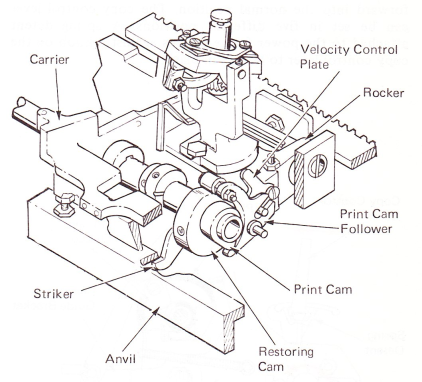
Figure 5 — Print Mechanism (Level 1)
PLATEN
The quality of typed impression is affected by the condition of the platen. Light, heat, chemicals, etc. may affect the platen rubber. An old or worn platen may not be consistent in diameter.
The platen is supported by the carriage guide brackets and held in position by the platen latches (Figure 6).
The platen may be removed by pressing the rear of the latches down and lifting the platen out. It may be installed without depressing the latches; however, caution must be taken to prevent bending the platen shaft. Releasing the feed roll tension will also aid in the installation of the platen.
COPY CONTROL LEVER
The copy control mechanism positions the platen front to rear to allow for different thicknesses of typing material. The copy control mechanism is operated by a lever located at the left end of the carriage (Figure 6). The lever is attached to a shaft that extends through the sides of the power frame. An eccentric collar attached to each end of the shaft operates between platen adjusting plates attached to the carriage end plate. As the lever is moved to the rear, the shaft rotates, causing the eccentric collars to force the carriage end plates to the rear. The platen and paper feed mechanism moves with the carriage end plates. When the copy control lever is pulled forward, the eccentric collars contact the platen adjusting plates and force the carriage forward into the normal position. The copy control lever can be set in five different positions. A spring detent attached to the power frame presses against a knob on the copy control lever to hold it in place.
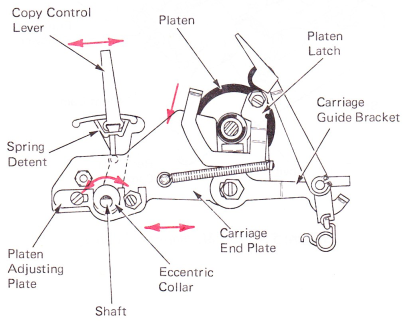
Figure 6 — Platen & Copy Control Lever (Left Side View)
DUAL VELOCITY SELECTION
On machines with dual velocity, selecting a low velocity character causes a pull on the velocity control cable to shift the roller to the low velocity side on the print cam (Figure 7). A low velocity vane is mounted in the keyboard in a position to be contacted by the selector interposer as it is driven forward by the filter shaft. Attached to the right end of the low velocity vane is the low velocity vane link. Rotation of the vane causes a pull on the link, causing the low velocity latch to rotate counterclockwise about its mounting stud. As the latch rotates, it pivots out of the operating path of the adjustable stop attached to the low velocity cam follower. The low velocity cam follower is spring loaded against the low velocity cam. With the low velocity latch removed from its operating path, the cam follower will move to the low spot of the low velocity cam, and cause a pull on the velocity control cable.
If a high velocity character is selected at the keyboard, the low velocity latch will remain at rest in the operating path of the stop on the cam follower. The cam follower is prevented from following the bend of the cam, and no pull is felt on the velocity control cable. The print cam follower roller remains to the right under the high velocity side of the print cam and a high velocity print operation results.
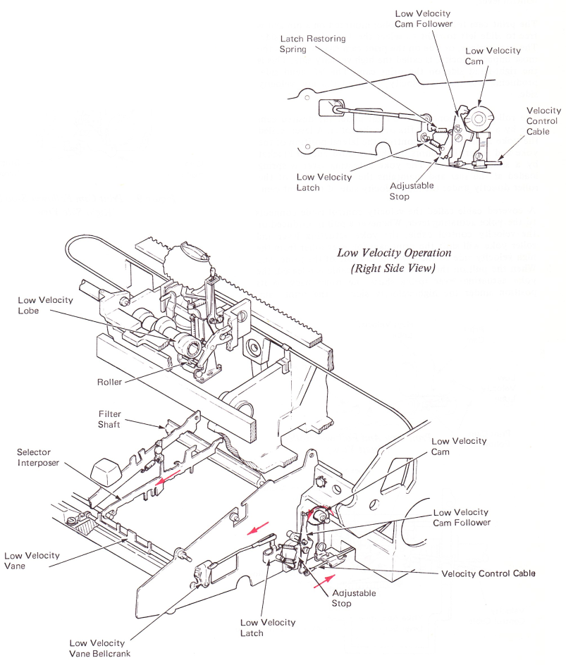
Figure 7 — Low Velocity Sequence
This is done by using a print cam that has two different cam surfaces (Figure 8). The low and high points of both cam surfaces are the same. The only difference is in the bend between their low and high points. The bend of one cam surface has less of a rise and provides the typehead with a lower impact velocity than the other. The difference in typehead velocities produced by the two cam surfaces remains proportional between all settings of the impression control lever.
The print cam follower has a roller mounted on a pin and is free to slide left to right to select the desired velocity side. The cam surface, or side on the print cam that produces the most impact velocity, is called the high velocity side. This is the right-hand side on the print cam. The left-hand side, producing less impact velocity, is called the low velocity side.
The roller is positioned left to right under the desired cam side by a roller yoke that fits over the roller. A lever, called the yoke actuating lever, controls the lateral position of the yoke and roller. It mounts on the tab cord anchor bracket by a shouldered rivet. The yoke actuating lever is spring loaded at the rear and maintains the rest position of the roller directly under the high velocity side of the print cam.
A covered cable called the velocity control cable connects to the yoke actuating lever. Whenever a pull is produced on the velocity control cable, the yoke actuating lever and roller yoke will shift the print cam follower roller from the high velocity side to the low velocity side of the print cam. When the pull on the velocity control cable is released, the yoke actuating lever spring shifts the roller back to its position under the high velocity side of the print cam.
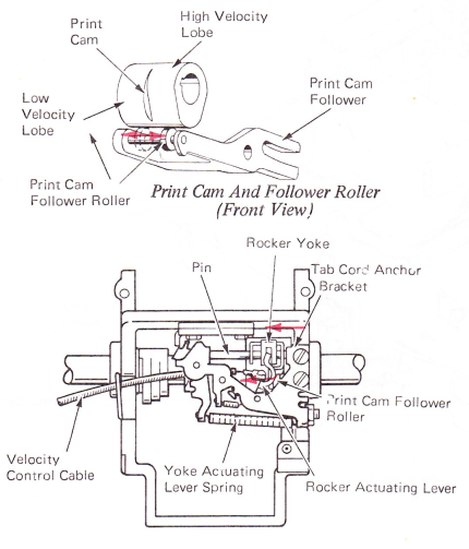
Figure 8 — Yoke Actuating Lever And Spring (Bottom View)
PRINT CAM FOLLOWER STOP SCREW
On the level 2 print mechanism,the print cam follower and roller are held disengaged from the print cam by an adjustable stop screw until the roller has shifted (Figure 9). This prevents the print cam from interfering with the print cam rollers as it shifts from one side to the other.
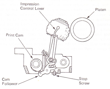
Figure 9 — Print Cam Follower Stop Screw (Right Side View