Selectric Resources
CARRIER RETURN ADJUSTMENTS
NOTE: All operational control adjustments must be correct before making carrier return adjustments.
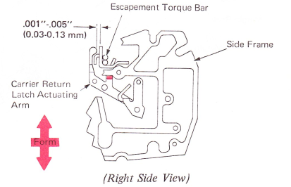
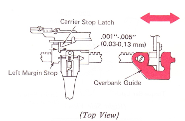
1. Carrier Return Latch Actuating Arm — Form the lug on the carrier return latch actuating arm so the vertical lug clears the lug on the escapement torque bar by .001”-.005”(0.03-0.13mm) at rest.
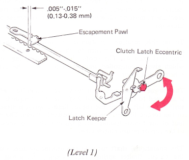
Level 1 machines can be identified by a clutch latch eccentric in the carrier return clutch latch. Level 3 machines can be identified by a 90-degree bend in the left-hand end of the clutch latch shaft. Other machines are level 2.
2. Pawl Clearance —
a. Level 1 — Adjust the clutch latch eccentric so the escapement pawl will clear the rack teeth by .005”-.015” (0.13-0.38 mm) when the latch is being held down by the keeper.
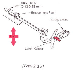
CAUTION: Do not form the tip of the carrier return clutch latch.
b. Level 2 And 3 — Form the tip of the carrier return clutch latch to get .005”-.015” (0.13-0.38 mm) between the escapement pawl and the escapement rack during a carrier return. This will allow the pawl to enter the rack quickly at the completion of a carrier return operation.
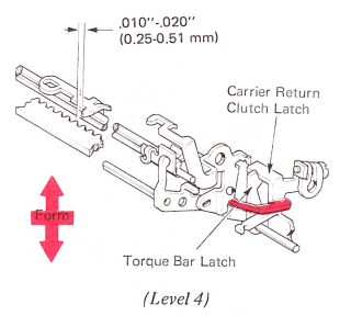
c. Level 4 — With the carrier return latched, form the clutch latch for .010”-.020” (0.25-0.51 mm) escapernent pawl clearance. Ensure that the torque bar latch is under the lug on the carrier return clutch latch.
NOTE: “Selectric” II NRB/S only.
3. Carrier Return Latch Height — Adjust the carrier return latch adjusting screw to get .001”-.015” (0.03-0.38 mm) clearance between the latch and the cam follower lever, The clearance should be kept to the low side to ensure a minimum of lost motion.

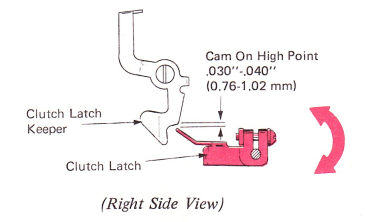
4. Clutch Latch Overthrow — Levels 1 And 2 — Adjust the adjusting screw in the carrier return latch arm to get .030”-.040” (0.76-1.02 mm) overthrow between the tip of the carrier return clutch latch and the clutch latch keeper with the carrier return/index cam on the high point.
Be sure the setscrew that locks the carrier return lever to the pivot shaft is tight, or there will not be enough carrier return latch overthrow.
NOTE: This adjustment should be made with the platen, deflector and feed rolls in the machine. After making this adjustment, be sure to recheck the carrier return latch height adjustment. This can be found in the Operational Control and Spacebar Section.
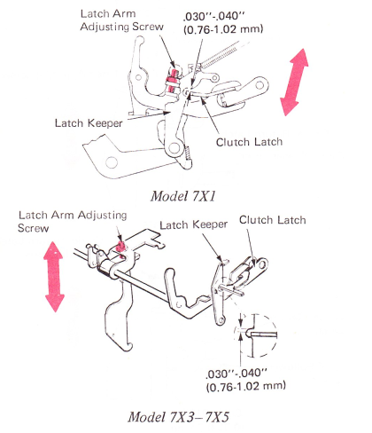
Level 3 — Rotate the clutch latch on the clutch latch actuating shaft to get .030”-.040” (0.76-l.02 mm) clearance between the carrier return clutch latch and clutch latch keeper. This adjustment should be made with the carrier return/index cam on the high point and the platen, deflector and feed rolls in the machine.
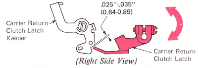
Level 4 — Rotate the clutch latch on the clutch latch actuating shaft to get .025”-.035” (0.64-0.89 mm) clearance between the carrier return clutch latch and clutch latch keeper. This adjustment should be made with the carrier return/index cam on the high point and the platen, deflector and feed rolls in the machine (NRB/S “Selectric” II only).
5. Carrier Return Shoe Overlap —
Level 1 — Adjust the carrier return actuating arm bracket left or right so the carrier return shoe overlaps the last three coils on the right-hand end of the carrier return clutch spring, and there is equal shoe to pinion spring contact on all three coils. This ensures that all coils of the clutch latch spring will be used in the clutch operation.
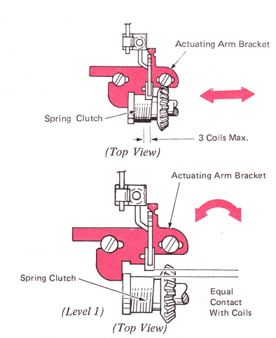
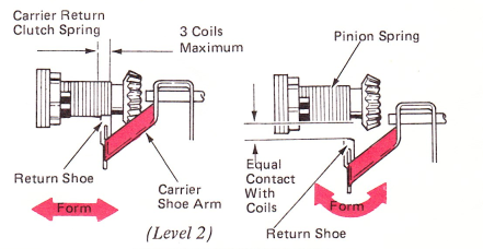
Level 2 — Form the one-piece carrier return shoe arm left or right so that the return shoe overlaps no more than the last three coils on the right-hand end of the carrier return clutch spring, and there is equal shoe to pinion spring contact on all three coils.
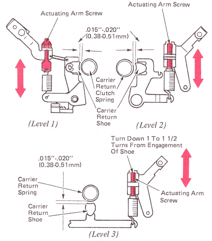
6. Carrier Return Shoe Clearance — Levels 1, 2 And 3 — Adjust the actuating arm spring screw vertically to get .015”-.020” (0.38-0.51 mm) clearance between the carrier return shoe and the carrier return clutch spring with all parts at rest.
NOTE: An easy way to get the clearance on Level 3 machines is to turn the arm actuating down 1 to 1-1/2 turns from engagement of shoe.
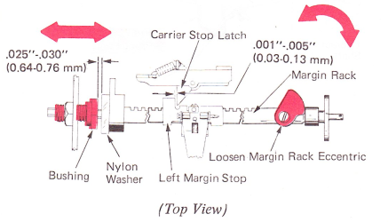
7. Overbank — Level 1 — With the carrier at the left-hand margin, adjust the margin rack eccentric to get .001”-.005" (0.03-0.13 mm) clearance between the left-hand margin stop and the carrier stop latch. Next, adjust the bushing at the left-hand end of the margin rack to get .025”-.030” (0.64-0.76 mm) between the bushing and the nylon washer.
NOTE: Any change in overbank on machines with this old-style margin rack assembly will directly affect the clutch unlatching adjustment.
Level 2 — With the carrier resting at the left-hand margin, adjust the overbank guide left-to-right to get .001”-.005” (0.03-0.13 mm) clearance between the left-hand margin stop and the carrier stop latch. The floating action of the stop latch must be removed by pulling the latch to the right with a springhook before this clearance can be observed.
NOTE: The play between the margin rack and rail on RB/S machines must be removed while making this adjustment. This is done by holding the margin rail to the right and the rack to the left.
The adjustment of the overbank guide on the margin rack determines the rest position of the margin rack. This adjustment ensures that the left-hand margin stop will set correctly when the stop is moved to the right against the carrier. The adjustment of the overbank guide, plus the amount of side motion that the guide allows, automatically provides the carrier with the overbank required for proper escapement pawl entry at the completion of a carrier return operation.
NOTE: Dual pitch machines must be checked in 12 pitch.
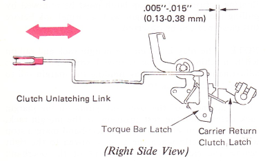
8. Clutch Unlatching — Adjust the clevis on the carrier return unlatching link so the clutch latch keeper clears the tip of the clutch latch by .005”-.015” (0.13-0.38 mm) on NRB/S and .001”-.010” (0.03-0.25 mm) on RB/S machines at the unlatching point. To observe this adjustment, turn the power on and hold the clutch latch down.
NOTE: On machines equipped with the early style margin rack, check the margin rack eccentric adjustment if the clutch fails to latch properly. The eccentric may be holding the rack too far to the left, limiting the margin rack motion and reducing the amount of overlap of the keeper on the latch.

Level 4 — With the margin rack held to the left, adjust the clutch unlatching link for .005”-.015” (0.13-0.38 mm) between the carrier return clutch latch and the torque bar latch.
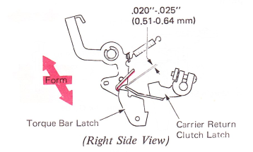
9. Torque Bar Latch — Level 4 Only — Form the lug on the torque bar latch so the carrier return clutch latch will overlap the carrier return clutch latch keeper by .020”-.025” (0.51-0.64 mm) when the carrier return is latched.
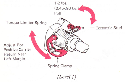
10. Torque Limiter — Level 1 — Adjust the eccentric stud on the torque limiter hub to provide one to two pounds pull on the carrier as the carrier is unlatching the clutch at the left-hand margin. If enough adjustment is not available at the eccentric, the torque limiter spring may be shifted on the torque limiter hub by repositioning the torque limiter spring clamp. If no spring scale is available, the torque may be estimated by holding the carrier while the clutch is engaged. The torque limiter should slip, but supply a positive carrier return when the carrier is released.
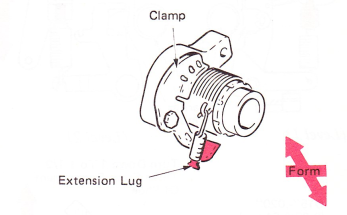
Level 2 — Form the extension lug on the clamp to provide one to two pounds pull on the carrier as the carrier unlatches the clutch at the left margin.
NOTE: This should be adjusted for positive carrier return when carrier is near the left margin.
If more adjustment is needed, the clamp can be positioned into another notch.
CAUTION: The spring lug extension may hit the carrier return shoe arm or the print interlock link when in full overthrow position. Form the tip of the spring lug down over the loop of the spring.
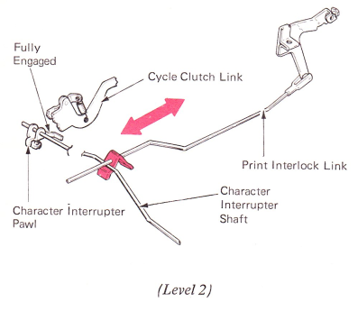
11. Carrier Return Interlock: — Level 1 — Form the carrier return print interlock link to satisfy the following conditions. With the carrier return clutch latched, the character interrupter pawl should fully engage in front of the cycle clutch link. With the carrier return mechanism at rest, the interlock link must not prevent the character interrupter shaft from returning to rest.
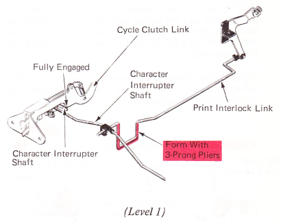
Level 2 — Adjust the clip front-to-rear on the carrier return print interlock link to satisfy the following conditions: With the carrier return clutch unlatched, the character interrupter pawl should fully engage in front of the cycle clutch link; with the carrier return mechanism at rest, the interlock link must not prevent the character interrupter shaft from returning to rest.