Selectric Resources
SWITCH PITCH OPERATIONAL THEORY,
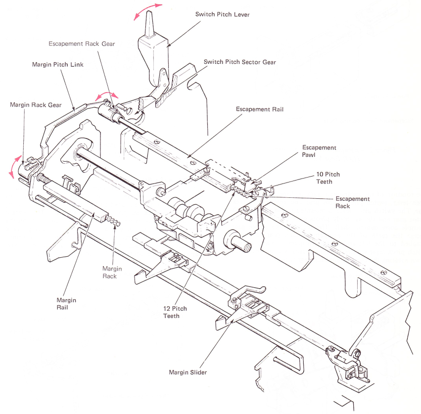
The purpose of the switch pitch mechanism is to perform the necessary switching operations within the escapement and margin mechanisms to allow the dual pitch “Selectric” II Typewriter to function properly in either 10 or 12 pitch. Both the escapement rack and margin rack are rods with teeth out into two sides. Ten pitch teeth and 12 pitch teeth are cut into both sides of the racks. The racks are held in slots in the escapement and margin rails, This puts the escapement rack teeth and the margin rack teeth in approximately the same position in the machine as the non-rotary backspace (NRB/S) escapement and margin rack teeth. Both the margin and escapement mechanisms function in the same way as the NRB/S “Selectric” Typewriter. Therefore, in order to switch pitch, it is necessary to rotate the racks until either the 10 pitch teeth or 12 pitch teeth face the rear of the machine and engage the escapement pawl and margin slider (Figure 1)
ESCAPEMENT RACK ROTATION
The escapement rail is attached to the power frame in the same way as the NRB/S “Selectric” Typewriter escapement rack. The horizontal rest position of the escapement rack is controlled by spring tension, loading the rack to the right end of the rail. The left end of the escapement rack extends through the escapement rack bearing plate which is mounted to the left side of the power frame (Figure 2).
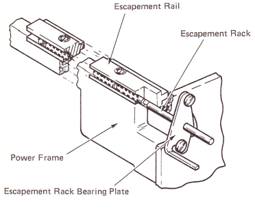
Figure 2 — Escapement Rack Mounting (Left Rear View)
The rotation of the escapement rack is done by the switch pitch lever, switch pitch sector gear and escapement rack gear. The switch pitch lever is mounted to the switch pitch sector gear and the assembly pivots on an extension of the multiple copy control shaft. The teeth of the sector gear engage the teeth of the escapement rack gear, which is attached to the left end of the escapement rack. As the switch pitch lever is operated, the sector gear moves up or down rotating the escapement rack gear (Figure 3).
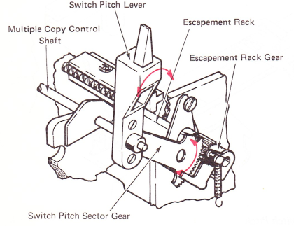
Figure 3 — Escapement Rack Gear And Switch Pitch Sector Gear (Left Rear View)
The escapement rack gear stop lug controls the two rest positions of the escapement rack. In the 10 pitch mode, the stop lug is spring loaded against the half backspace lever mounting stud by the escapement rack gear toggle spring. When the gear is switched to the 12 pitch mode, it moves over and the stop lug is spring loaded against a lug on the escapement rack bearing plate (Figure 4).
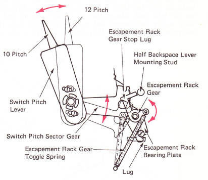
Figure 4 — Escapement Rack Rotation (Left Side View)
MARGIN RACK ROTATION
The left end of the margin rack is mounted in a bushing that is held in a hole in the power frame. The right end of the margin rack is mounted in the overbank guide bracket. The margin rack supports the margin rail. The margin release bracket is mounted to the margin rail. A lug on the margin release bracket engages a notch in the margin rack causing the rack and the rail to move left-to-right as a unit. The left-to-right position of the margin rack/rail and overbank motion are controlled by the overbank guide (Figure 5).
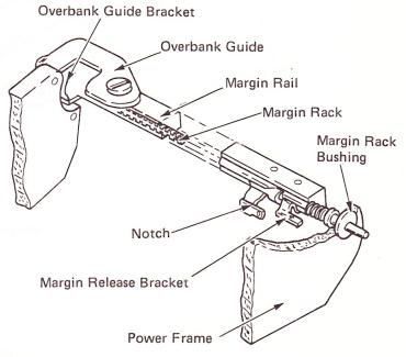
Figure 5 — Margin Rack Mounting (Left Rear View)
The margin rack is rotated by the margin pitch link and the margin rack gear. The teeth of the margin pitch link engage the teeth of the margin rack gear which is attached to the left end of the margin rack. The rear end of the margin pitch link is mounted to the escapement rack gear. As the escapement rack gear is rotated, the margin pitch link moves front-to-rear rotating the margin rack gear (Figure 6).
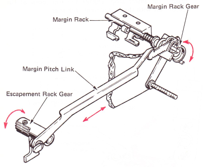
Figure 6 — Margin Pitch Link And Margin Rack Gear (Left Rear View)
The two rest positions of the margin rack gear are controlled by two stops on the margin pitch link guide bracket. A lug on the margin rack gear is moved and spring loaded against the stops in the same way as the escapement rack gear (Figure 7).
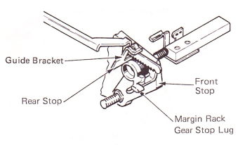
Figure 7 — Margin Rack Rotation (Left Front View)