Selectric Resources
SWITCH PITCH ADJUSTMENTS
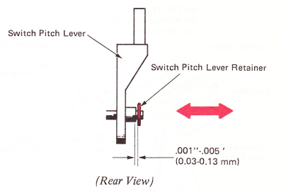
1. Switch Pitch Lever — Adjust the retainer for .001”-.005” (0.03-0.13 mm) end play of the switch pitch lever.
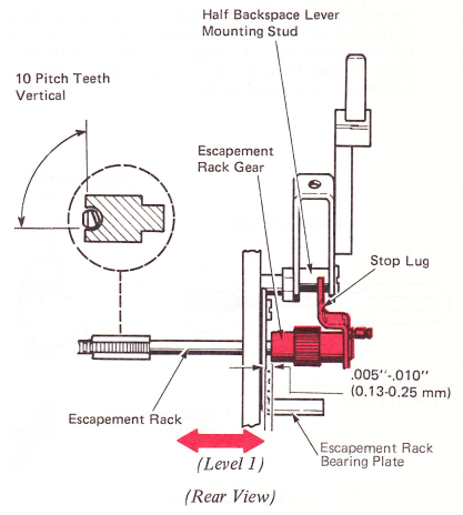
2. Escapement Rack Gear — With the escapement rack gear stop lug against the half backspace lever mounting stud, adjust the 10 pitch escapement rack teeth vertical.
Level 1 — A clearance of .005”-.010” (0.13-0.25 mm) must be maintained between the escapement rack gear and the escapement rack bearing plate when tightening the setscrews.
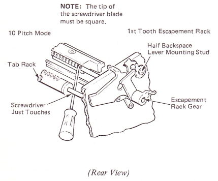
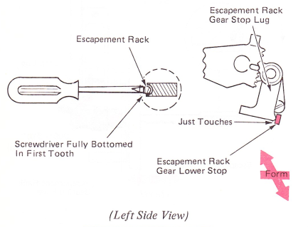
Levels 2 And 3 — The gear should be positioned left to right to be flush against (no clearance) the half backspace cam. This can be done as follows: Loosen the escapement rack gear. Insert the blade of a small three-inch screwdriver in the first tooth on the left end of the rack. Raise the screwdriver until it touches the tab rack shaft and lightly hit the screwdriver until it is fully bottomed in the tooth and the rack stops rotating; then, tighten the rack gear. This procedure will ensure the rack teeth are vertical.
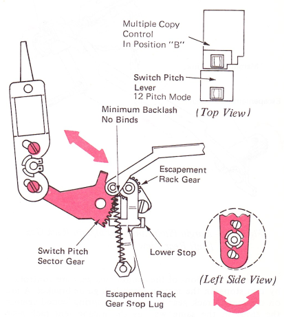
3. Escapement Rack Gear Lower Stop — With the machine in 12 pitch, form the lower stop toward the front of the machine and insert the small three-inch screwdriver in the first tooth of the escapement rack and lightly hit the screwdriver until it is fully bottomed and the rack stops rotating. Form the lower stop until it touches the escapement rack gear stop lug.
4. Switch Pitch Sector Gear, Level 1 — With the escapement rack gear stop lug against the lower stop, engage the switch pitch sector gear with the escapement rack gear so the upper two teeth do not engage. Adjust for minimum backlash with no binds. The switch pitch lever should be positioned to be parallel to the multiple copy control lever in the “B” position.
Level 2 — With the escapement rack gear stop lug against the lower stop, engage the top tooth of the sector gear with the escapement rack gear.
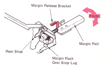
5. Margin Rail Horizontal — Form the margin release bracket so the margin rail rests in a horizontal position.
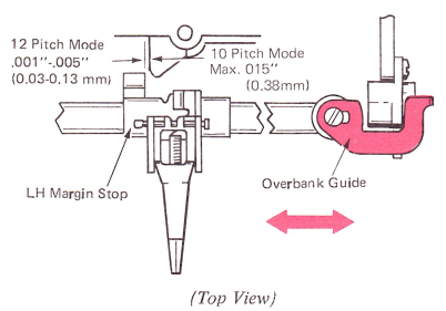
6. Overbank — With carrier at the left margin, position the overbank guide left or right for .001”-.005” (003-013 mm) between the carrier stop latch and the left margin stop in the 12 pitch mode. In the 10 pitch mode, the clearance must not be more than .015” (0.38 mm). Make sure the margin rack gear does not interfere with this adjustment.
NOTE: While making this adjustment, it is necessary to remove all motion of the rack within the rail to the left. This can be done by holding the rail and moving the rack to the left with the right margin slider.
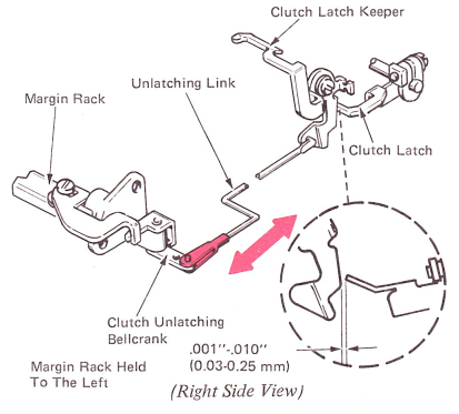
7. Clutch Unlatching Link — Adjust the carrier return clutch unlatching link for .001”-.010” (0.03-0.25 mm) between the latch with the carrier in the full overbank position.
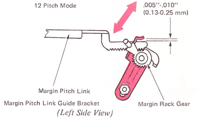
8. Margin Pitch Link Guide Bracket — Adjust the margin pitch link guide bracket up or down for .005”-.010” (0.13-0.25 mm) clearance between the guide bracket lug and the top edge of the margin pitch link. Make this adjustment with the machine in the 12 pitch mode; engage the first tooth of the margin pitch link with the first tooth of the margin rack gear. This adjustment allows the margin pitch link to give minimum backlash and not bind with the margin rack gear.
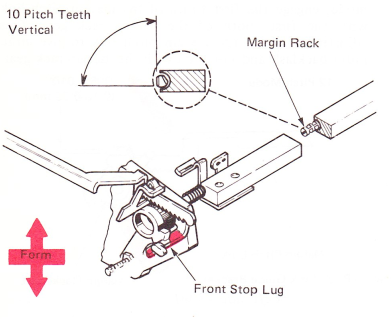
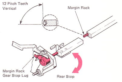
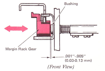
9. Margin Rack Gear — With the margin rack gear against the rear stop, rotate the margin rack until the 12 pitch teeth are vertical. Maintain .001”-.005” (0.03-0.13mm) clearance between the margin rack gear and the bushing when tightening the setscrews.
NOTE: When adjusting the margin switch pitch gear end play, it is necessary to remove all of the motion of the rack within the rail to the left. This can be done by holding the rail and moving the rack to the left with the right margin slider.
10. Front Margin Rack Gear Stop — Form the front margin rack stop lug so the ten pitch margin rack teeth are vertical in the ten pitch mode.