Selectric Resources
ESCAPEMENT (NRB/S) OPERATIONAL THEORY
The purpose of the escapement mechanism is to control the single space movement of the carrier during each print cycle (Figure 1). The non-rotary backspace (NRB/S) escapement mechanism uses a backspace rack to provide the motion for carrier backspace.
The carrier is under constant mainspring tension. At rest, the escapement pawl, which is mounted on the carrier, engages the escapement rack and prevents the mainspring from pulling the carrier to the right. During an escapement operation, the pawl is pulled out of the rack and the carrier moves to the right under mainspring tension until the pawl engages the next tooth on the escapement rack.
Power to operate the escapement mechanisms is taken from the escapement cam, mounted on the filter shaft just inside the right-hand power frame (Figure 1). Each time a cycle occurs, the filter shaft rotates the cam 180 degrees.
The escapement cam follower pivots on a shaft just to the rear of the escapement cam. A trip link extends to the rear, from the cam follower to the trigger lever.
Each time the filter shaft turns, the escapement cam follower will pivot, pulling on the trip link, causing the trigger lever to rotate about the mounting shafts.
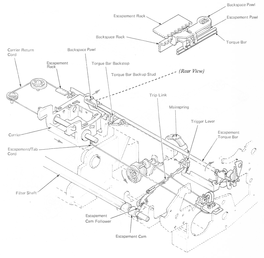
Figure 1 — Escapement Mechanism
TRIGGER OPERATION
An escapement trigger is mounted on the trigger lever (Figure 2). The trigger has hooked-shaped lugs that rest above a lug on the right end of the torque bar. During each escapement operation, the rotation of the trigger lever causes the trigger to move downward. This downward movement of the trigger causes the torque bar to rotate.
The torque bar pivots between the sides of the power frame, just to the rear of the escapement rack.
The pivot point of the torque bar is near its bottom edge. The escapement pawl and the backspace pawl each have a lug that extends down just behind the torque bar. As the top of the torque bar pivots to the rear, the torque bar will force the pawls to the rear, causing the tips of the pawls to clear their racks.
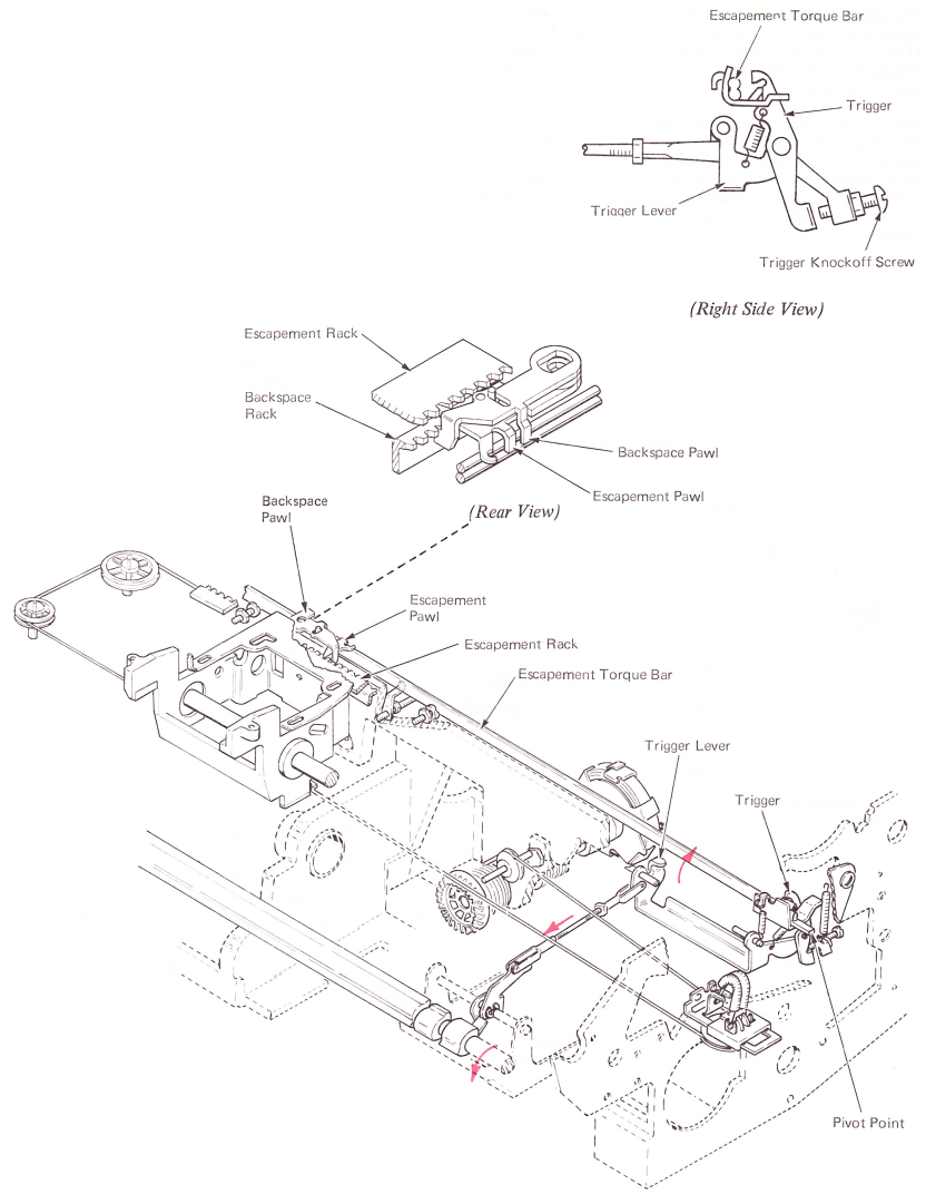
Figure 2 — Trigger Operation
OPERATING SEQUENCE
An escapement operation occurs by forcing the escapement pawl to the rear, out of engagement with the rack tooth. Due to the slot in the mounting hole, as soon as the pawl clears the escapement rack tooth, it is pulled quickly to the right by the pawl spring. The escapement pawl is allowed to move to the front into engagement with the next tooth. The carrier then moves to the right until it comes to rest against the escapement pawl.
Figure 3 shows the escapement and backspace pawls and their racks. The pivot stud is attached to the bracket mounted on the carrier.
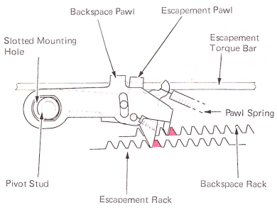
Figure 3 — Pawl At Rest (Top View)
The carrier is always being pulled to the right, and the pivot stud is against the right edge of the elongated slot in the pawls.
Figure 4 shows the torque bar operated. The pawls have been pulled free of their racks and the spring tension has pulled the pawls to the right before the carrier has started to move.
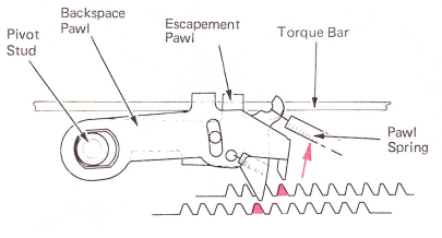
Figure 4 — Torque Bar Operated (Top View)
In Figure 5, the torque bar is returning to the rest position and the pawls are dropping into the next tooth of their racks. The carrier has not moved.
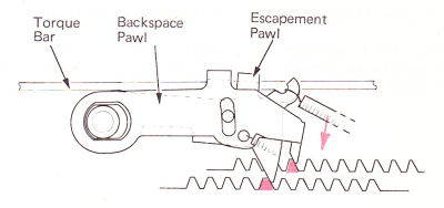
Figure 5 — Pawls Returning To Rest (Top View)
In Figure 6, the carrier has moved to the right and the pawls have stopped the pivot stud, and again the carrier is at rest after moving one space.
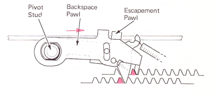
Figure 6 — End Of Operation (Top View)
NOTE: The carrier and escapement pawl must be moved to the left for a backspace operation. Because the backspace pawl is mounted to the escapement bracket, movement of the backspace pawl to the left forces the carrier and escapement pawl to the left. The backspace pawl is mounted just above the escapement pawl, but the backspace tooth extends below the escapement pawl and is held engaged with the backspace rack by a small extension spring.
The backspace rack is mounted to the rear of the power frame by shouldered screws through elongated holes in the rack. This mounting arrangement allows lateral movement of the rack. Movement of the rack to the left forces the backspace pawl to the left to cause a backspace operation.
The backspace operation is pointed out here due to the close connection with the escapement mechanism. The backspace pawl is engaged with the rack when in the rest position. This means that both the backspace and escapement pawls must be removed from their racks in order for the carrier to move to the right.
ESCAPEMENT TORQUE BAR
Because of the force required to pull the pawls out of their racks, the torque bar bends to the front instead of pushing the pawls to the rear. This is stopped by the use of a backup stud mounted to the center power frame (Figure 7).
On level 1 machines, the pawl pivot stud extending down from the escapement bracket in front of the escapement torque bar stops this bending.
On XX3 and XX5 machines, an additional support is given to the escapement torque bar to prevent it from bending to the rear. A backstop mounted to a stud in the machine power frame provides the support.
NOTE: On long carriage machines, an additional backup stud can be mounted on the left side of the power frame to give the escapement torque bar additional support.
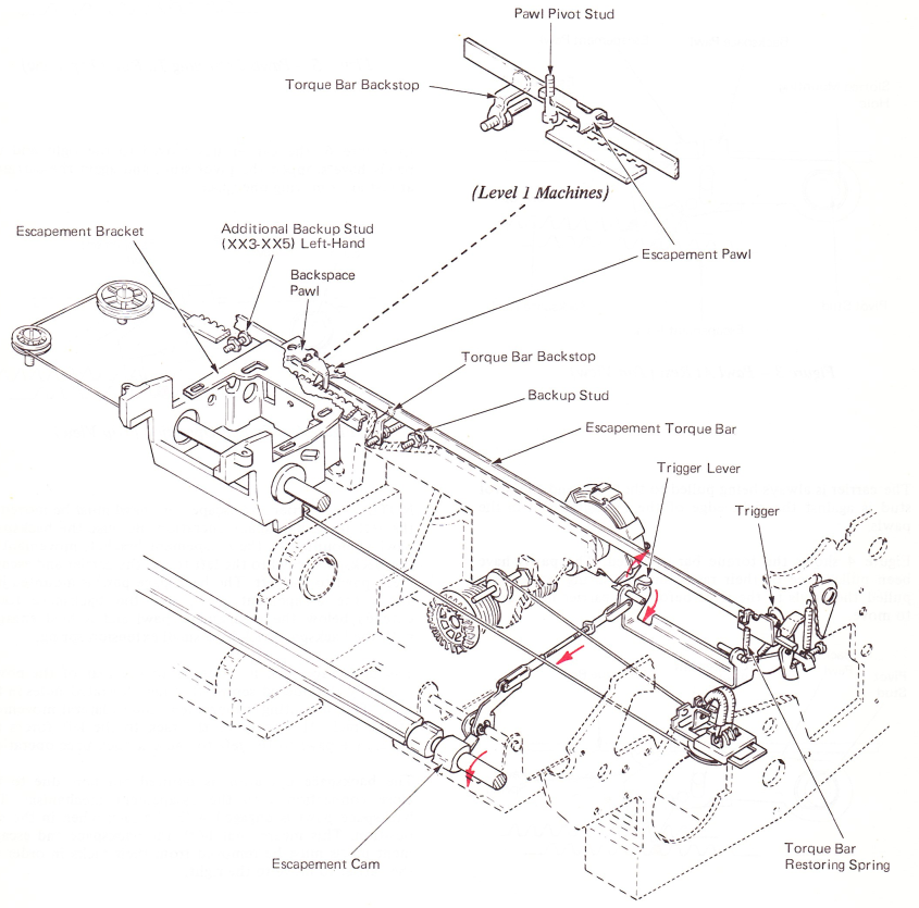
Figure 7 — Escapement Torque Bar
TRIGGER KNOCKOFF
Rotation of the escapement torque bar supplies just enough motion to remove the pawls from their racks. The torque bar is immediately rotated back to the rest position by a restoring spring located at the right-hand end. This allows the pawls to re-enter their racks to limit the carrier movement to one space (Figure 8).
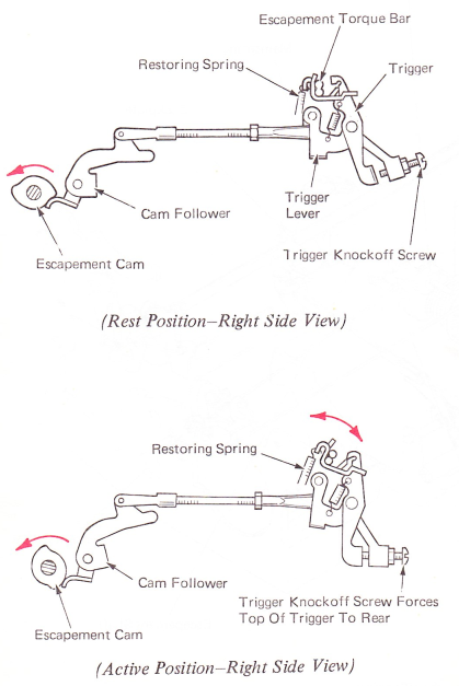
Figure 8 — Trigger Knockoff
Timing is important in this type of escapement. The torque bar must return to rest before the carrier has moved enough to skip a tooth on the racks.
The trigger lever is operated by motion transmitted from the escapement cam. Therefore, it can only restore as quickly as the cam can rotate from the high point to the low point. To prevent the escapement pawl from skipping, the torque bar must be allowed to restore more quickly.
An adjustable knockoff screw causes the trigger to cam off of the torque bar lug just after the pawls have been removed from the rack. The torque bar can then restore without waiting for restoring of the trigger and the trigger lever.
Level 1 machines are equipped with an adjustable knockoff eccentric stud (Figure 9). The stud serves the same purpose as the trigger knockoff screw and will be covered in the escapement adjustment summary.
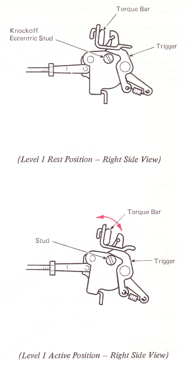
Figure 9 — Trigger Knockoff (Level 1)
CARRIER MOVEMENT
The mainspring is mounted near the back of the machine and engages the escapement shaft (Figure 10).
The escapement shaft extends forward through a backplate and the power frame. Located on this shaft are two drums. The escapement/tab cord is wound several turns around the escapement cord drum, then to the right over a guide roller just before passing through the right side of the machine. The cord passes around a tension pulley and back through the power frame and connects to the right-hand side of the carrier.
The carrier return cord is wound in the opposite direction around the carrier return cord drum, passes around two pulleys and connects to the left side of the carrier. Mainspring tension is applied to the carrier through the escapement tab cord to move the carrier to the right during an escapement operation. As the escapement cord drum winds up cord, the carrier return cord drum unwinds cord. This allows the tension pulley to maintain constant tension on the carrier and also allows the mainspring to be rewound during a carrier return operation.
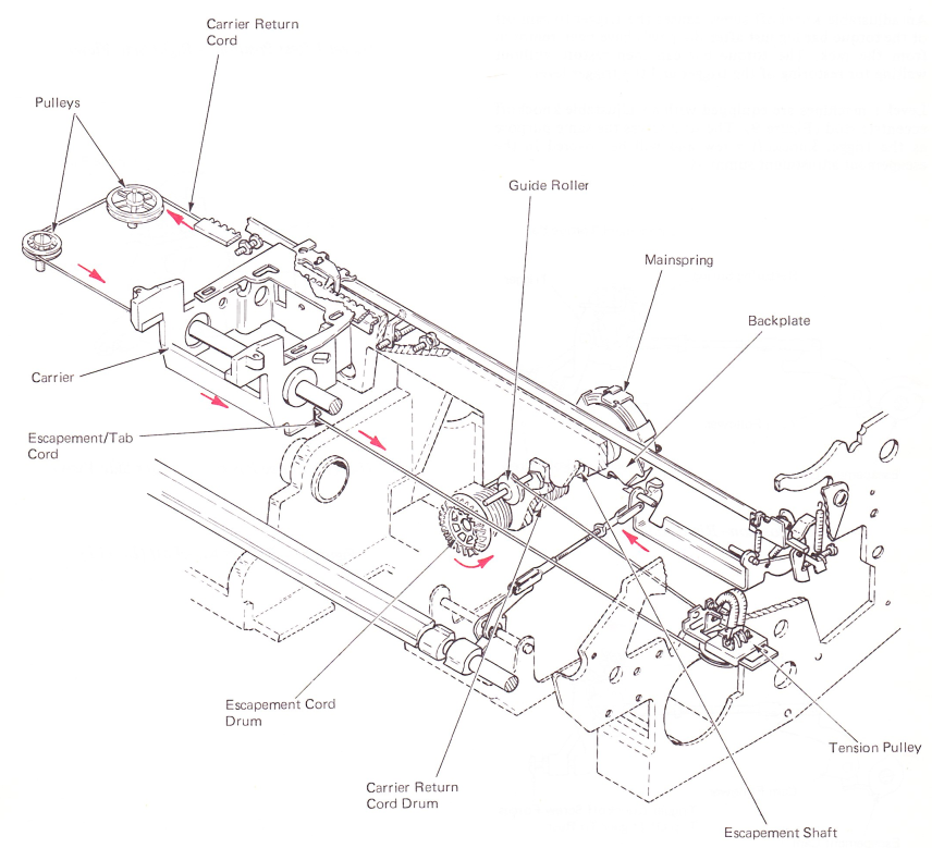
Figure 10 - Mainspring Tension