Selectric Resources
SHIFT OPERATIONAL THEORY
The purpose of the shift mechanism is to rotate the typehead 180 degrees in the counterclockwise direction. This places the uppercase part of the typehead near the platen for typing uppercase letters. Each uppercase character is in the same tilt and rotate band as the lowercase character, but 180 degrees from it.
The shift mechanism consists of a shift arm, shift cam, spring clutch, clutch control mechanism and interlocks.
Two keybuttons, one at each front corner of the keyboard, can be used to operate the shift mechanism. A bail is used to connect the two keylevers together. The left-hand keylever has a lock mechanism attached to it to allow the operator to lock the keybutton down in the uppercase position. The shift lock may be released by depressing and releasing either shift keybutton.
The power to operate the shift mechanism is taken from the right-hand end of the operational shaft (Figure l).
Motion of the shift bail is transferred through the shift release bellcrank and shift release link to operate the release arm. The release arm controls the shift ratchet and clutch spring to allow the shift cam to rotate.
Depressing the shift keybutton causes the shift cam to rotate, forcing the shift arm to move away from the power frame. This supplies enough pull on the rotate tape to rotate the typehead 180 degrees to the uppercase position.
Releasing the shift keybutton allows the shift keylevers to be returned to their rest position by the shift keylever spring and causes the shift cam to return home. The shift arm moves toward the power frame and the spring tension on the rotate tape system returns the typehead to the lowercase position.
NOTE: The rotate tape and pulley system is covered under the character selection section of this manual.
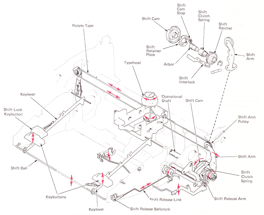
Figure 1 — Shift Mechanism
SHlFT ARM
The right-hand rotate pulley is attached to the top of the shift arm. The shift arm pivots left to right about a pin at the bottom. At the center of the shift arm is a roller that rides the surface of the shift cam. In the lowercase position, the shift arm rests against the head of an adjustable stop screw on the side of the power frame (Figure 2).
The shift cam is a disc-shaped cam that has the working surface on the right side of the cam rather than on the outer surface (Figure 2).
A backup button (pressed out on a section of the shift bearing plate) directly opposite the roller on the shift arm serves as a backing for the cam.
When the shift cam is operated, the high point of the cam is contacted and forces the shift arm away from the power frame, rotating the typehead 180 degrees into the uppercase position.
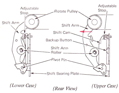
Figure 2 — Shift Cam And Shift Arm
Early level machines are equipped with a backup roller mounted to the shift bearing plate (Figure 3). The backup roller serves the same purpose as the pressed out button and is covered further in the shift adjustment section.
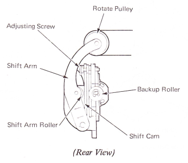
Figure 3 — Shift Cam Backup Roller
SHIFT CLUTCH
The shift cam rotates only during a shift operation and is controlled by a spring clutch. One end of the spring clutch is held to the shift cam by an adjustable retainer plate. The other end of the shift clutch spring is mounted to the shift ratchet (Figure 4)
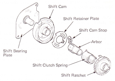
Figure 4 — Shift Clutch
SHIFT CLUTCH RELEASE
The shift ratchet has two lugs sticking out on the left side approximately 180 degrees from each other (Figure 5). One lug is closer to the center of the ratchet than the other lug. The shift clutch release arm, pivoted just in front of the cam, blocks the lugs to stop the rotation of the ratchet. The position of the shift release arm is positioned by a link connected between the shift clutch release arm and the shift release bellcrank attached to the shift bail. When the keylevers are at rest, the release arm is in a position to contact the inner lug of the shift ratchet. Depressing the keylever causes the clutch release arm to rise out of the path of the inner lug into the path of the outer lug. This allows the spring clutch to tighten around the shift arbor and drive the Shift cam until the outer lug of the shift ratchet is contacted.
The overthrow of the shift cam is controlled by an adjustable stop attached to the cam and operates against the inner lug of the shift ratchet.
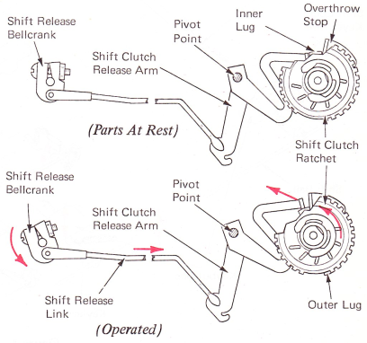
Figure 5 — Shift Clutch Mechanism (Right Side View)
SHIFT CAM BRAKE
Shift cam overthrow is a greater problem in returning the machine to lowercase than in shifting to uppercase. This is due to the increased speed received from the pressure of the shift arm roller against the shift cam as it turns to the cam low point. To prevent excessive noise and possible parts breakage, a raised surface on the shift cam contacts a shift cam brake arm. The brake arm bends and works like a heavy spring when returning to lower case and prevents the increased speed of the shift cam (Figure 6).
NOTE: Early level machines have a nylon shoe mounted on the shift cam brake where it contacts the shift cam.

Figure 6 — Shift Cam Brake — (Right Side View)
SHIFT DETENT AND CHARACTER INTERRUPTER
Pivoted on a stud in front of the shift cam is the shift detent arm. The shift detent arm detents the shift cam in position and operates the character interrupter mechanism. The character interrupter mechanism prevents the operation of a character when the shift is operating. The character interrupter pawl is rotated into the path of the cycle clutch latch pawl and prevents the release of the cycle clutch. This interlocking action does not prevent the operation of a keylever or an interposer. The interposer is latched down into storage. When the shift operation is completed, the detent enters a slot in the cam removing the character interrupter pawl from in front of the cycle clutch latch link (Figure 7).
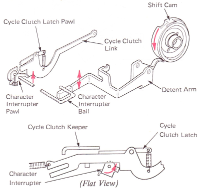
Figure 7 — Character Interrupter (Right Side View)
SHIFT INTERLOCK
If the shift mechanism is operated during a print character cycle, the shift interlock prevents the shift from operating until the character cycle is completed. The shift interlock operates from a cam mounted to the filter shaft. Each time the filter shaft turns, the shift interlock is positioned into the shift clutch ratchet to prevent a shift operation (Figure 8).
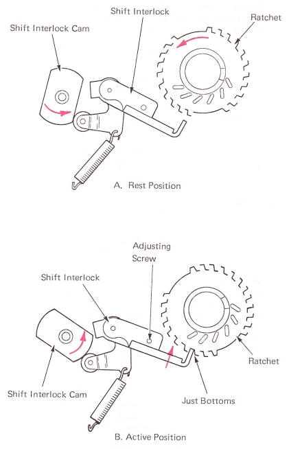
Figure 8 — Shift Interlock (Right Side View)