Selectric Resources
SHIFT ADJUSTMENTS
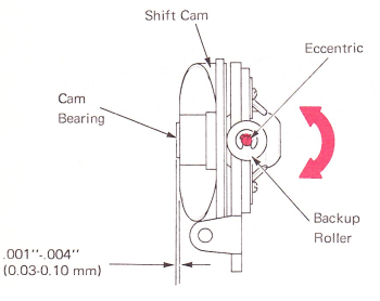
1. Shift Cam Backup Roller (Early Level Machines Only) — Adjust the backup roller eccentric left to right so .001”-.004” (0.03-0.10 mm) of the cam bearing extends past the cam. The eccentric should be kept in the bottom half of the rotation.
CAUTION: Any change in the rest position of the backup roller, directly affects the typehead rotate adjustment and the shift arm motion adjustments. Be sure to recheck these adjustments.
(Rear View)
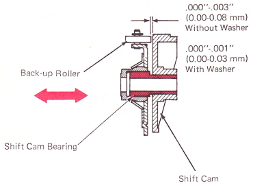
2. Shift Cam Bearing (Early Level Machines Only) — Adjust the shift cam bearing left-to-right to get a clearance of .000”-.003” (0.00-0.08 mm) between the shift cam and the shift cam backup roller. Machines equipped with a washer between the shift cam and bearing plate should be adjusted for a clearance of .000”-.001”(0.00-0.03mm).
(Top View)
NOTE: Machines above S/N 7X1-5805429; 7X3-5277541; 7X5-5623384 do not have adjustments 1 and 2.
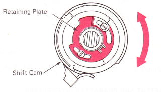
3. Shift Spring Clutch Retaining Plate — Adjust the retaining plate around the shift cam so the ratchet will rotate one and one-half to two teeth when released and with the machine off and the shift cam in the uppercase rest position. Readjust so that shift cam detents reliably into uppercase position.
Check this adjustment by holding the shift detent away from the shift cam. After a shift cycle, allow the detent roller to contact the shift cam. The detent should not move the cam more than .030” (0.76 mm) in either direction when the detent is fully bottomed in its detent notch (check both shift cycles).
NOTE: Machines equipped with Level 1 metal shift cams require one tooth rotation of the shift ratchet when released. Machines with plastic and sintered steel cams require 1-1/2 to 2 teeth rotation of the ratchet when released from upper case.
(Right Side View)
4. Shift Overthrow Stop — Adjust the shift overthrow stop to get .010”—.030” (0.25-0.76 mm) clearance between the stop and the inner lug of the shift ratchet, with all parts at rest. Shift to upper case. The clearance must be the same.

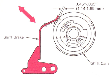
5. Shift Brake — Adjust the shift brake to get .045”-.065” (0.89-1.02 mm) rise as the brake contacts the working surface of the shift cam.
(Right Side View)
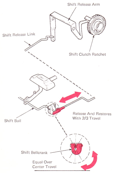
6. Shift Release — Position the shift bellcrank on the shift bail to have the same over center movement in both directions. Adjust the shift release link so release occurs when the keylever is depressed two-thirds of the way down. As the keylever is allowed to restore from a fully depressed position, the shift should again operate when two-thirds movement of the keylever has been reached. Equal movement between the two releasing points ensures proper adjustment.
7. Shift Lock — Adjust the shift lock bracket vertically so the shift lock engages just as the shift operates or slightly after. The lock should not engage before the shift release occurs. The shift lock must be released easily by depressing either shift keybutton.

(Right Side View)
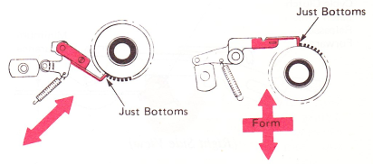
8. Shift Interlock — Adjust the interlock so the tip of the interlock just bottoms between two teeth on the ratchet with the interlock follower on the high point of the interlock cam. Adjust the interlock by the adjusting screw on XX3—XX5 machines to satisfy this condition or form the interlock on 7X1 machines.
(Right Side View)
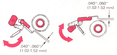
9. Shift Interlock Cam — Adjust the interlock cam until a clearance of .040”-.060” (1.02-1.52 mm) exists between the tip of the interlock and the top of the tooth on the shift clutch ratchet, with the cycle clutch latched at rest and all backlash of the cycle shaft and filter shaft removed in the operating direction.
CAUTION: Be sure the interlock cam is in the correct section of its rotation. This can be checked by operating the cycle clutch and hand cycling a character. The interlock must move toward the shift ratchet immediately.
(Right Side View)
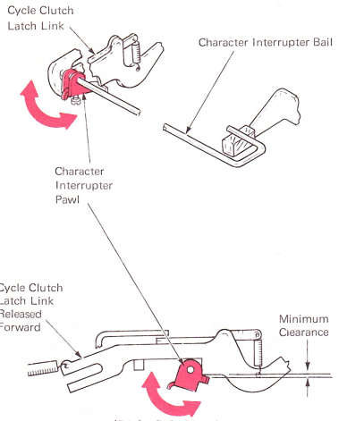
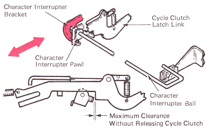
10. Character Interrupter — Adjust the character interrupter to satisfy the following conditions:
a. Adjust the interrupter pawl on the interrupter bail for minimum clearance between the interrupter pawl and the cycle clutch latch link when the cycle clutch latch link is in the released position and the shift is at rest.
(Right Side View)
b. Adjust the interrupter bracket front-to-rear to get maximum clearance between the interrupter pawl and the cycle clutch latch link when the shift is partially operated. This clearance should not be wide enough to allow the cycle clutch to operate.
(Right Side View)