Selectric Resources
MOTOR AND DRIVE ADJUSTMENTS
1. Cycle Shaft End Play — Adjust the collar on the shaft for .001”-.006” (003-015 mm) end play of the cycle shaft.
CAUTION: The slight end play of the cycle shaft ensures that it will rotate freely. Excessive play could allow a coil of the cycle clutch spring to bind between the two hub parts of the clutch causing the machine to become locked.

2. Gear Train Backlash — Adjust the upper and lower idler gears for minimum backlash between the gears. The mechanism must be free of binds during the 360 degrees rotation of the gears. Minimum backlash is necessary to ensure minimum overthrow of the driven shafts. The lower idler gear must be adjusted first because the upper idler gear is adjusted to the final
position of the lower gear.
NOTE: Filter shaft and print shaft timing must be checked after making this adjustment.

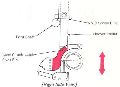
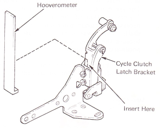
3. Cycle Clutch Latch Bracket — Adjust the bracket vertically so the Hooverometer, set on the No. 3 line, just reaches the distance between the print shaft and the cycle latch pivot pin.
NOTE: Recheck the cycle clutch latch restoring adjustment after changing this adjustment.
4. Cycle Clutch — Adjust the cycle clutch to satisfy the following conditions:
a. Loosen the cycle clutch collar and position the spring to clear the edge of the cycle clutch hub by .004”-.012”(0.10-0.30 mm).
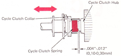
NOTE: The cycle clutch spring must be installed
with the longer lug to the left.
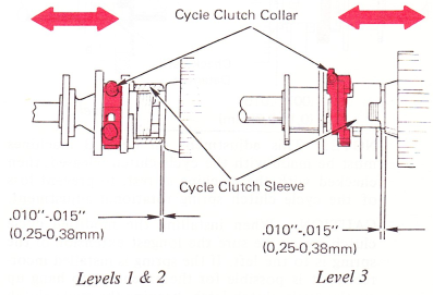
b. Position the collar left-to-right for .010”-.015” (0.25-0.38 mm) end play of the sleeve.
c. When a zero tilt, negative five rotate character is hand cycled, adjust the collar and spring rotationally so the cycle clutch spring will begin to slip when the print shaft is 1/2-1 tooth from the rest position.
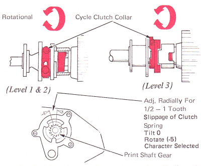
d. Position the overthrow stop so it will allow the cycle shaft to overthrow the latched position by .007”-.015”(0.18-0.38mm).

NOTE: This adjustment on Level 3 machines must be made with the cycle clutch released; then checked with the machine at rest, to prevent loss of the cycle clutch spring rotational adjustment.
CAUTION: When installing the modified cycle clutch spring, be sure the longest extension of the spring is to the left. If the spring is installed incorrectly, it is possible for the extension to hang up on the cycle clutch latch, keeping the cycle clutch from unlatching.
POWER ON ADJUSTMENT PROCEDURE
The cycle clutch adjustments may be made with the power on as described in the following procedure.
Pre-Conditions:
The cycle shaft, filter shaft and print shaft must be properly timed.
The gear train backlash must be correct.
The rest of the machine must be functional.
The right-hand shield must be in place while performing this power on adjustment. This will remove the danger of the splined wrench being thrown out of the machine due to the possibility of it contacting the turning torque limiter hub. Rotation of the cycle clutch pulley and drive belt does not present a hazard as there are no exposed parts which could throw the splined wrench out of the machine.
a. Turn machine on, position the cycle clutch collar screw up, then position the carrier into the RH margin to lock the keyboard which will prevent cycling of the cycle shaft.
b. Insert the L shaped foot of the Hooverometer into the cycle clutch latch link to prevent unexpected cycling of the machine.
c. Loosen the cycle clutch clamp screw and advance print shaft (top-to-rear).
CAUTION: Do not operate the cycle clutch with the splined wrench in the clamp screw.
d. Check for .004”-.012” (0.10-0.30 mm) clearance between the right side of the spring and the edge of the cycle clutch hub. Expand the spring by pushing the LH side of the spring with a spring hook and move the spring laterally for this adjustment.
e. Rotate the print shaft a complete cycle (top-to-rear) until the cycle shaft check pawl drops in. Back the cycle shaft up against the check pawl.
f. Position the collar left-to-right for .010”-.015” (0.25-0.38 mm) end play of the sleeve.
g. Position the overthrow stop for .007”-.015” (0.18-0.38 mm) clearance and tighten the clamp screw. This will give approximately 1/2 tooth of motion to “unwind” the spring from the rest position. Observe this motion at the print shaft gear by hand cycling a zero tilt, negative five character with the power off.
5. Drive Belt — Adjust the motor mounting brackets front-to-rear for a minimum amount of belt noise. The belt must not be loose enough to allow the belt to slip on the motor pulley. Check by operating the carrier return mechanism and holding the carrier while operating the shift mechanism at the same time. This loads the motor to a point where failure will be most probable.

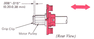
6. Motor Pulley — Adjust hub assembly and grip clip left-to-right so the belt runs fully on both pulleys. Maintain .008”-.015” (0.20-0.38 mm) pulley end play with grip clip.
NOTE: Make certain the plastic bushing is installed in the motor pulley.
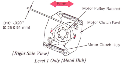
7. Motor Clutch Pawl Stop Lugs (Level 1 Only) — Form the stop lugs on the clutch hub for a clearance of .010”-.020” (0.25-0.51 mm) between the tip of the clutch pawls and the pulley ratchet when the pulley is manually rotated.