Selectric Resources
SELECTIVE RIBBON OPERATIONAL THEORY
The purpose of the selective ribbon system is to operate with the film ribbon, the IBM Tech III ribbon or the IBM High Yield Correctable Film Ribbon. All three of these ribbons are contained in a cartridge, similar to the “Selectric” Typewriter fabric ribbon cartridge, but much larger. The complete supply of ribbon is in the left side of the cartridge. The used ribbon will be wound around the take-up core on the right side and the cartridge will be thrown away when the ribbon is used up. The cartridges for the three types of ribbons look the same but have different color take-up knobs and leaders for identification. Blue is used for IBM Tech III, pink for film and orange for the IBM Correctable Film Ribbon (Figure 1).
The feed modes for the IBM High Yield Correctable Film Ribbon and film ribbon are the same, but the feed mode for the IBM Tech III ribbon differs completely. The film ribbons must be fed so that no characters overlap, but the IBM Tech III ribbon is fed in much smaller amounts so as to use the overstrike feature of this ribbon. The inner construction of the cartridge determines in which ribbon feed mode the mechanism will operate.
A ribbon lift pattern of three tracks is used for all three of the ribbons. However, the IBM Tech III ribbon lift is changed slightly to maintain even color.
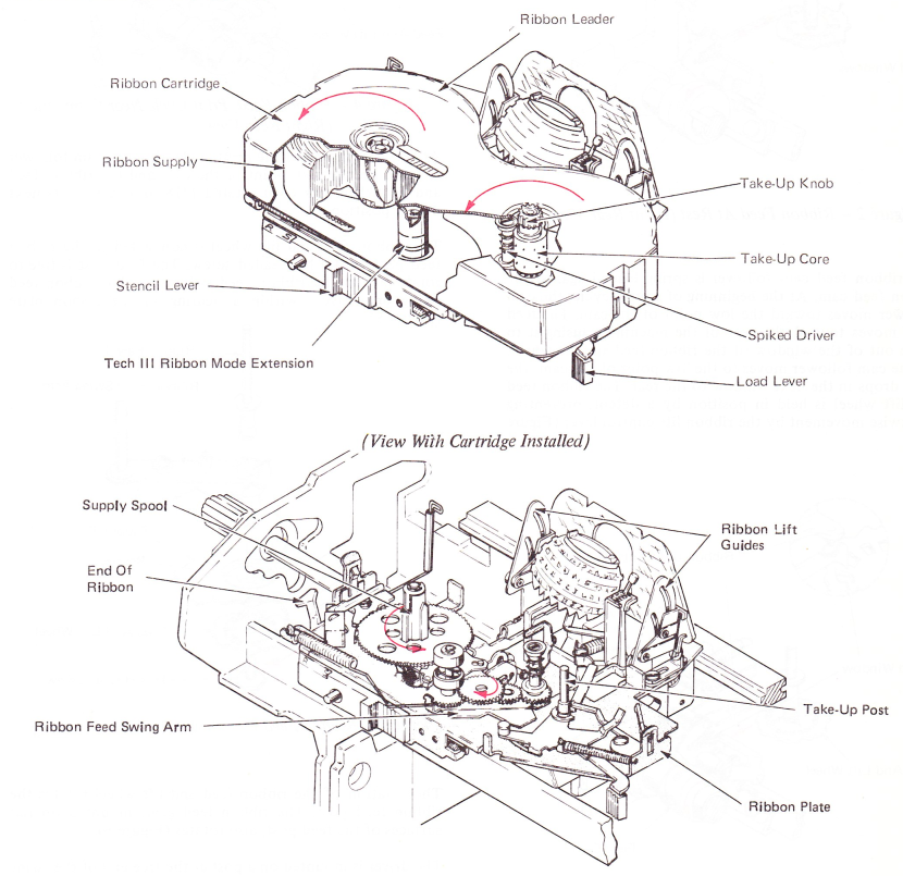
Figure 1 — Selective Ribbon System
RIBBON FEED
Ribbon feed is performed by the ribbon feed cam follower assembly operating a ribbon feed pawl. During a print cycle, the ribbon feed pawl operates in one of the eighteen feed windows on the ribbon feed and lift wheel, rotating it in a counterclockwise direction. At rest, the ribbon feed cam follower is on the high point of the ribbon feed cam and the ribbon feed pawl is engaged in one of the feed windows (Figure 2).
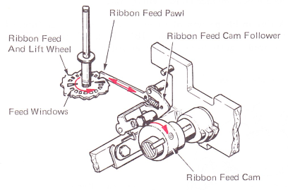
Figure 2 — Ribbon Feed At Rest (Right Rear View)
The ribbon feed cam follower is spring loaded against the ribbon feed cam. At the beginning of a print cycle, the cam follower moves toward the low point of the cam. The feed pawl moves toward the rear of the machine, causing it to move out of the window of the ribbon feed and lift wheel. As the cam follower moves to the low point of the cam, the pawl drops in the next window to the rear. The ribbon feed and lift wheel is held in position by a detent, preventing clockwise movement by the ribbon lift control lever (Figure 3).
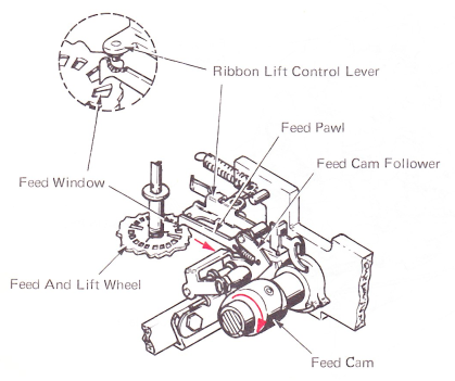
Figure 3 — Ribbon Feed, Early Stages Of Print Cycle (Right Rear View)
As the print cycle completes, the cam follower rises toward the high point of the cam, moving the pawl toward the front of the machine. The pawl operates against the front surface of the window, rotating the ribbon feed and lift wheel in a clockwise direction (Figure 4).
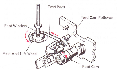
Figure 4 — Ribbon Feed, Print Cycle Near Completion (Right Rear View)
At the completion of the print cycle, the feed cam follower is again on the high point of the cam and the ribbon feed and lift wheel has been rotated 1/18 of a turn to its next detent position.
The ribbon feed and lift wheel is connected to the ribbon feed post with a hexheaded screw. The feed post is free to rotate within the ribbon feed swing arm. The ribbon feed swing arm pivots within a bearing in the ribbon plate (Figure 5).
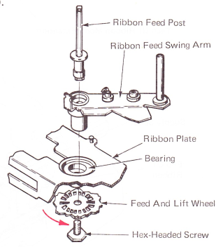
Figure 5 — Ribbon Feed Post And Swing Arm Mounting
The rotation of the ribbon feed and lift wheel rotates the ribbon feed post. The ribbon feed gear, mounted on flat surfaces of the feed post, also rotates (Figure 6).
The driver is mounted on a post at the free end of the swing arm. Two intermediate gears mounted on the swing arm transfer the feed gear rotation to the driver.
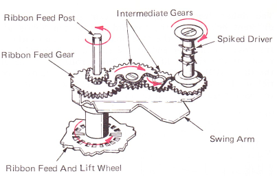
Figure 6 — Spiked Driver Rotation
The free end of the swing arm is heavily spring loaded toward the ribbon takeup post. This causes the points of the driver to engage the used ribbon. When the driver rotates, it causes the takeup core to rotate about the takeup post, winding up the used ribbon and pulling new ribbon into the print position (Figure 7).
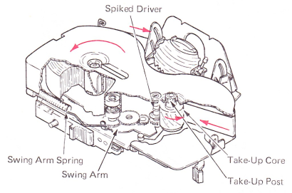
Figure 7 — Ribbon Feed Operation
FILM RIBBON MODE
The different feed amounts for the two ribbon modes are controlled by the amount of driver rotation for each print cycle.
The ribbon feed gear is free to slide vertically on the ribbon feed post. Its vertical position determines the amount of driver rotation. In the film ribbon mode, the ribbon feed gear is spring loaded up by the feed gear spring allowing its large gear to engage the small gear of the first intermediate gear. This causes the spiked driver to rotate enough to feed film ribbon so the characters do not overlap (Figure 8).
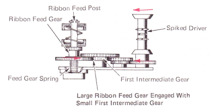
Figure 8 — Film Ribbon Mode
IBM TECH III RIBBON MODE
In the IBM Tech III ribbon mode, an extension within the cartridge depresses the ribbon mode button which, through a compression spring, depresses and holds down the ribbon feed gear. This allows the small gear on the ribbon feed gear to engage the large gear of the first intermediate gear and causes the driver to rotate approximately 1/6 the amount as in the film ribbon mode (Figure 9).
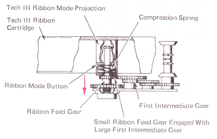
Figure 9 — IBM Tech III Ribbon Mode
The ribbon must be kept slightly tight through the ribbon path for proper feeding and tracking. This is done by the ribbon shock wire which is used as a detent on the ribbon supply spool. The ribbon supply spool is not allowed to rotate until the ribbon applies enough tension on the shock wire to release the detent. As more ribbon is supplied, some tension is released from the shock wire allowing the detent to bottom in the teeth of the supply spool (Figure 10).
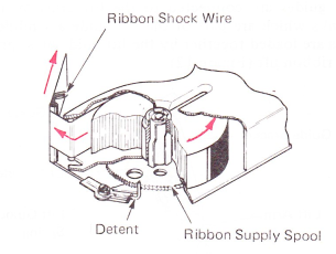
Figure 10 — Ribbon Tension Spring
RIBBON LIFT
All three of the ribbons used with this mechanism are slightly less than 11/16” (17.5 mm) wide. In order to get the maximum number of characters from the ribbon, the mechanism will use three different ribbon lift positions. The ribbon lift mechanism includes a lift cam, lift cam follower assembly, lift control lever, lift arm and lift guide assemblies (Figure 11).
The lift cam follower pivots above and to the rear of the lift cam. A lift spread adjusting plate is mounted to the cam follower by two small screws. A lug on the adjusting plate contacts the head of the height adjusting screw in the lift arm. As the cam follower is pivoted by the lift cam, it supplies vertical motion to the lift arm.
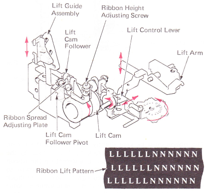
Figure 11 — Ribbon Lift Assembly
The ribbon is passed through the ribbon lift guides, which can move vertically in curved slots in the lift guide brackets. The lift guides are connected to the lift arms by the lift guide links which are part of the lift guide assemblies. The lift arms are loaded together by the lift guide bias springs to prevent ribbon lift (Figure 12).
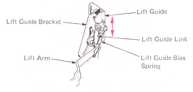
Figure 12 — Ribbon Lift Guide Assembly
The three ribbon lift positions are determined by the lift cam, which has three different height surfaces. The lift cam follower receives a different amount of motion from each surface (Figure 13).
The ribbon lift cam follower roller is free to slide on its shaft. Its side position is controlled by a yoke on the ribbon lift control lever. A stud on the forward end of the ribbon lift control lever is spring loaded against the cam surface of the ribbon feed and lift wheel.
The ribbon feed and lift wheel cam surface has three different heights. As the forward end of the ribbon lift control lever follows the feed and lift wheel cam surface, the yoke on the rear end of the ribbon lift control lever positions the ribbon lift cam follower roller over one of the three SIDES of the ribbon lift cam. This changes the ribbon lift from high lift to medium lift to low lift and back to high lift again to repeat the cycle.
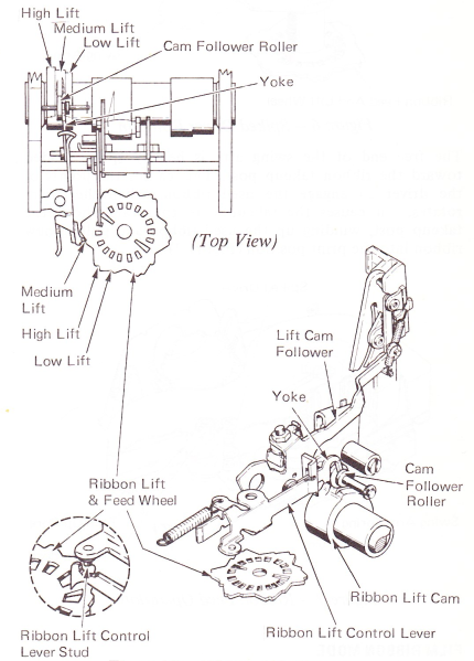
Figure 13 — Ribbon Lift Operation
In the IBM Tech III ribbon mode, the ribbon lift pattern is changed (wobbled) slightly to ensure even print color. This is done by the wobbler cam, the wobbler bellcrank and the wobbler eccentric. The left pivot point of the ribbon lift arm assembly is the wobbler eccentric. The wobbler eccentric has a vertical lug that extends above the surface of the ribbon plate. Moving this lug front to rear causes the wobbler eccentric to rotate, moving the left lift arm pivot point up or down (Figure 14).
The wobbler bellcrank pivots on a stud on the ribbon plate just to the left rear of the ribbon feed gear. The tip of the left wobbler bellcrank arm rests in an opening in the vertical lug of the wobbler eccentric. The ribbon lift arm spring loads both the wobbler eccentric lug and the wobbler bellcrank arm toward the front. If the mechanism is in the IBM Tech III ribbon mode, the wobbler bellcrank arm moves front to rear, moving the wobbler eccentric lug front to rear.
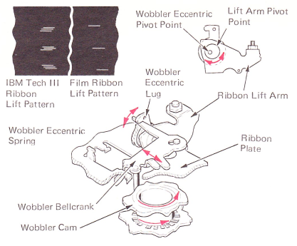
Figure 14 — Ribbon Lift Wobble Mechanism
The wobbler mechanism is active only in the IBM Tech III ribbon mode. The front of the wobbler bellcrank is free to move vertically. Its vertical position is controlled by two lugs on the wobbler bellcrank contacting the ribbon feed gear. When the feed gear is pressed down into the IBM Tech III ribbon mode by the cartridge, it also moves the wobbler bellcrank down into the operated position. When the wobbler bellcrank is in the operated position, a stud on the forward end of it follows the wobbler cam which is mounted directly above and turns with the ribbon feed and lift wheel. The motion from the wobbler cam rotates the wobbler bellcrank, which operates the wobbler eccentric, causing the desired changes in the ribbon lift pattern (Figure 15).
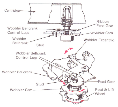
Figure 15 — IBM Tech III Mode — Wobbler Active
When the mechanism is in the film ribbon mode, the feed gear is up. This allows 3 lug on the wobbler bellcrank to be latched against the ribbon plate, causing the bellcrank to be inactive (Figure 16).
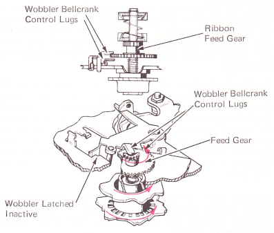
Figure 16 — Film Ribbon Mode — Wobbler Inactive
STENCIL MODE
When the typewriter is used for typing stencils, the ribbon feed and lift operations must be locked out. This is done by moving the stencil lever left to the stencil position. The lever will latch in the stencil position and can be released by pushing the release button. A lug on the stencil lever contacts an extension on the front of the lift control lever, moving the rear of the lift control lever to the right. This moves the lift cam follower roller completely off the lift cam, inhibiting ribbon lift (Figure 17).
When the lift control lever is in the stencil position, a feed lockout lug on it moves behind the feed pawl mounting stud. This prevents rear movement of the feed pawl, inhibiting ribbon feed.
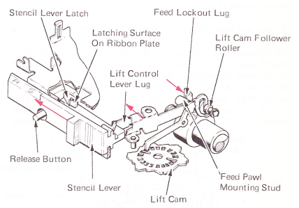
Figure 17 — Stencil Operation
RIBBON LOAD
When the ribbon needs to be changed, the load lever is moved to the left to the load position. An angled surface on the load lever contacts a lug on the right front of the lift arm assembly. This moves the front of the lift arm down and raises the lift guides for easier ribbon installation (Figure 18).
During the loading of a ribbon, the operator must be prevented from turning the takeup core in the wrong direction. the takeup core interlock extends to the left from the right cartridge retaining spring. In the load position, the takeup core interlock engages the teeth on the takeup core, preventing it from being rotated in a clockwise direction. In the normal operating position, the takeup core interlock is held away from the takeup core by a lug on the load lever.
The load lever latch will not allow the load lever to restore to the operate position until a cartridge is installed. This depresses the latch and allows the load lever to be restored to the operate position.
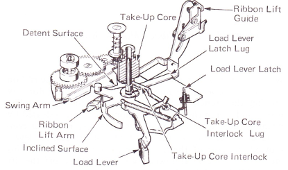
Figure 18 — Load Lever Operation
As the swing arm moves to the load position, it contacts the wobbler bellcrank, rotating it clockwise. This positions the wobbler bellcrank so that when it restores, it will latch against the ribbon plate in the film ribbon mode or easily move down into the operated position in the IBM Tech III ribbon mode (Figure 19).
As the wobbler bellcrank rotates, its left arm moves the lug of the wobbler eccentric to the rear. The wobbler eccentric lug contacts the right arm of the shock wire disengage lever which pivots on the supply spool post. The left arm of the shock wire disengage lever follows the cam surface of the shock wire. As the left arm moves to the front, it moves the shock wire detent from the ribbon supply spool. This action is necessary to allow the operator to easily wind the leader on to the takeup core when installing a ribbon.
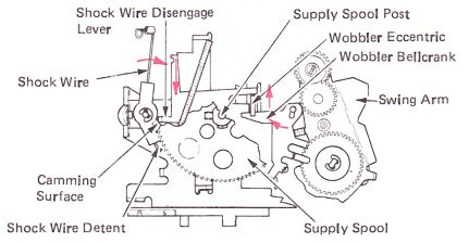
Figure 19 — Load Operation — Wobbler — Release — Shock Wire Disengage (Top View)