Selectric Resources
FABRIC RIBBON ADJUSTMENTS
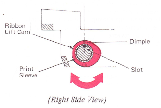
1. Ribbon Lift Cam — Adjust the ribbon lift cam so the aligning slot on the print sleeve lines up with the front edge of the print sleeve keyway.
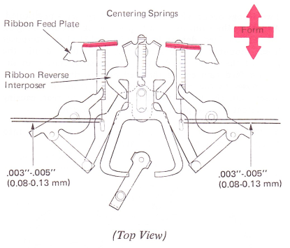
2. Centering Spring (Level 1 Only) — With the ribbon reverse interposer centered, form the lugs of the ribbon feed plate for .003”-.005” (0.08-0.13 mm) clearance in the centering spring loops. This adjustment ensures that the springs are not extended when at rest and that they will properly restore the mechanism after a reverse operation,
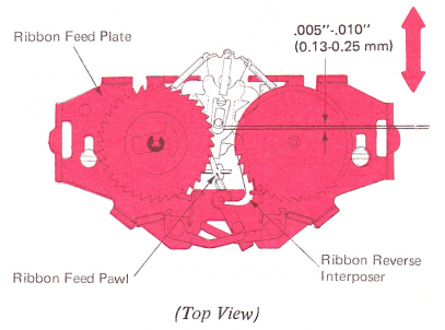
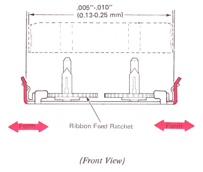
3. Ribbon Feed Plate (Level 1 Only) — With the ribbon mechanism set for a reversing operation and the ribbon cam at its high point, adjust the feed plate forward or back on the carrier so the ribbon feed pawl holds the reverse interposer within .005”-.010” (0.13-0.25 mm) of its total motion. This adjustment not only ensures enough throw for a reversing operation, but also gives maximum ribbon feed results by determining the rest and active positions for the pawl.
CAUTION: After completing the adjustment, manually cycle a character to see that two teeth are fed plus .005”-.010” (0.13-0.25 mm) overthrow. Be sure that the feed pawl does not contact the interposer lever as the pawl is manually reversed from side to side.
4. Cartridge Guide Lugs — Form the cartridge guide lugs so the cartridge spools will be centered over the ratchets. Side play of the cartridge must be limited within .005”-.010” (0.13-0.25 mm).
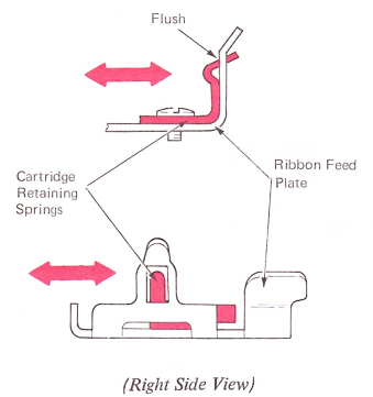
5. Cartridge Retaining Springs (Level 2 Only) — The cartridge retaining springs should be positioned laterally so they are FLUSH against the feed plate; then adjust front-to-rear so the cartridge retaining fingers are centered in the holes of the cartridge guide lugs. The ratchet brake part of the spring should put a small drag on the feed ratchet. Form only as necessary.
NOTE: Excessive or not enough tension could result in reverse failure.
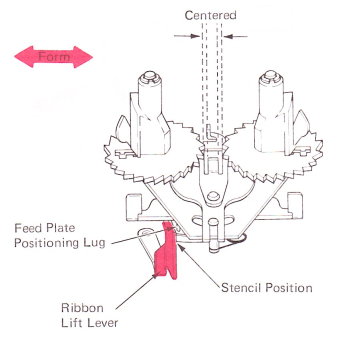
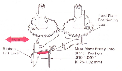
6. Ribbon Lift Lever (Level 2 Only) — Three conditions must be met as follows:
a. Form the ribbon lift lever finger tab left or right so the ribbon feed pawl will center between the two feed ratchets when the lift lever is placed in stencil position.
b. Form the rear lug so a clearance of .010”-.040” (0.25-1.02 mm) exists between the lug and the feed plate positioning lug when the LEFT RATCHET IS FEEDING.
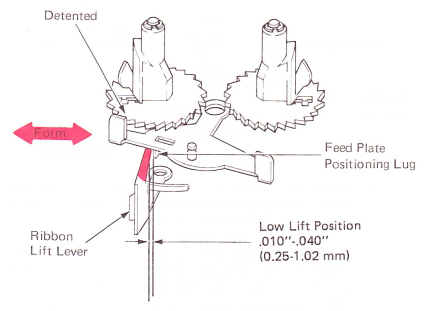
c. Form the front lug so a clearance of .010”-.040” (0.25-1.02 mm) exists between the lug and the feed plate positioning lug when the RIGHT RATCHET IS FEEDING.
NOTE: Do not form the ribbon feed plate positioning lug, since breakage would require replacement of the whole feed plate.
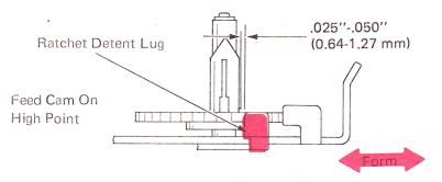
7. Ratchet Detent Lever Lugs — These should be formed as follows:
a. Left or right so the ribbon feed ratchet tooth overthrows the edge of the detent lug by .025”-.050” (0.64-1.27 mm) when hand cycling to the high point of the ribbon feed cam.
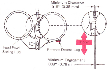
b. Form the detent lugs front-to-rear so the ribbon feed pawl engages a ratchet tooth by approximately one-half of the ratchet tooth.
NOTE: The feed pawl spring lug should clear the teeth of the opposite ratchet by at least .015” (0.38 mm) when the feed pawl is being moved to the rest position at the end of an operation. Failure to clear the teeth of the opposite ratchet under power may result in a locked mechanism and failure of the ribbon feed operation.
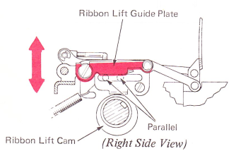
8. Ribbon Lift Guide Plate — Adjust the plate as low as possible without causing a change in the ribbon lift guide height as the ribbon lift lever is moved from the low lift to the high lift position. The ribbon lift cam should be at the low point when the check is made.
This adjustment ensures the same amount of throw for both the high and low lift position.
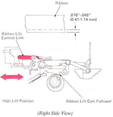
9. Ribbon Lift Control Link — Adjust the link forward or back by means of its clevis so the underscore will strike the ribbon .016”-.045” (0.41-1.14 mm) from the bottom edge. The ribbon lift lever must be in the high lift position when this check is made.
CAUTION: Do not adjust the link so short that it binds off the front end of the cam follower slot as the ribbon lift lever is moved into the high lift position.
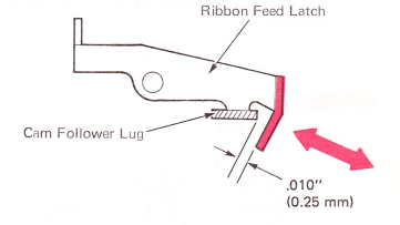
10. Stencil Lockout (Level 1 Only) — With the lift lever in the stencil position and the cam follower on the high point of the ribbon feed cam, form the ribbon feed latch for .010” (0.25 mm) clearance with the lug on the cam follower.