Selectric Resources
SELECTIVE RIBBON ADJUSTMENTS
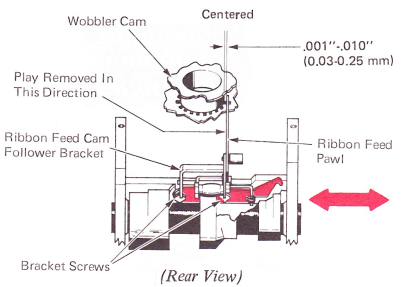
1. Ribbon Feed Cam Follower Bracket — Adjust the ribbon feed cam follower bracket left or right so the ribbon feed pawl is centered in the window of the wobbler cam.
This adjustment will ensure that the feed pawl will not
bind against the wobbler cam and will not move
past the outside limits of the feed window.
The bracket screws can be accessed from below by removing one of the cable anchor bracket screws and pivoting the cable anchor out of the way.
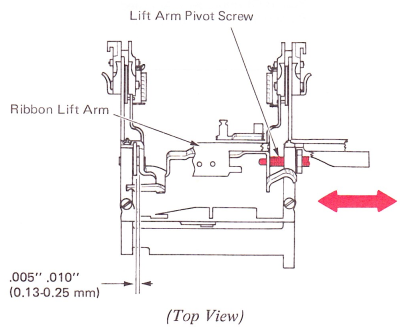
2. Ribbon Lift Arm — Adjust the right-hand lift arm pivot screw for .005”-.010” (0.13-0.25 mm) play of the lift arm. Make this adjustment with the wobbler eccentric lug in an up position.
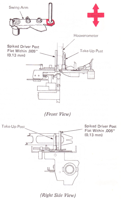
3. Spiked Driver Post — The spiked driver post must be parallel to the takeup post within .005" (0.13 mm). This must be checked in two ways.
NOTE: The swing arm spring should be connected while making these checks.
a. Hold the Hooverometer edge flat against the takeup post. Allow the swing arm to close until the spiked driver post contacts the other edge of the Hooverometer. The spiked driver post should be flat to the Hooverometer edge within .005” (0.13 mm).
b. Place a flat surface (such as an aligning wrench) against the takeup post and spiked driver post. The posts should both be flat to the surface within .005” (0.13 mm).
Form the free end of the swing arm to get these conditions. The symptom of an out of parallel condition will be a bind within the cartridge caused by the used ribbon binding. This could cause feed failures.
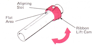
4. Ribbon Lift Cam — Adjust the ribbon lift cam so the aligning slot is aligned with the front edge of the print sleeve keyway.
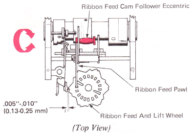
5. Ribbon Feed Cam Follower Eccentric — Adjust the ribbon feed cam follower eccentric to cause the ribbon feed pawl to drive the ribbon feed and lift wheel .005”-.010” (0.13-0.25 mm) past the detent position on a high side of the ribbon feed and lift wheel cam surface. Keep the eccentric in the lower front half of its orbit.
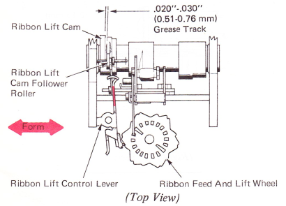
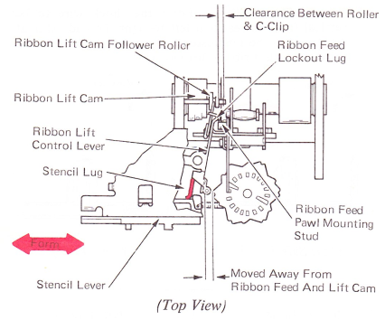
6. Ribbon Lift Control Lever — Position the ribbon feed and lift wheel detent in the medium lift position (center cam surface). Form the ribbon lift control lever to position the left edge of the ribbon lift cam follower roller .020”-.030” (0.51-0.76 mm) from the edge of the high lift side. This may also be observed by putting grease on the ribbon lift cam and observing the roller track in the grease on the medium lift cam surface.
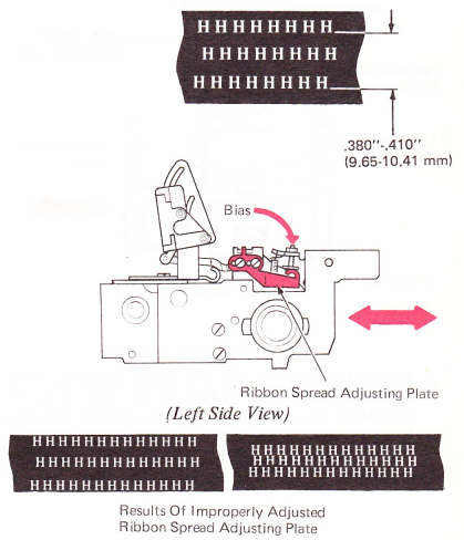
7. Ribbon Spread Adjusting Plate — In the film ribbon mode, adjust the ribbon spread adjusting plate to rear to get .380”-.410” (9.65-10.41 mm) from the bottom of a high lift character to the bottom of a low lift character. This may be measured with the aid of the Hooverometer handle which is .375” (9.52 mm) wide. The play in the ribbon spread adjusting plate must be removed in a clockwise direction as viewed from the left side of the carrier when tightening the binding screws. This is easily done by tightening the screws with the machine half cycled. This takes out the play in the mounting holes in the direction of the lifting force and ensures that the adjustment does not change. Ribbon height must be checked after making this adjustment.
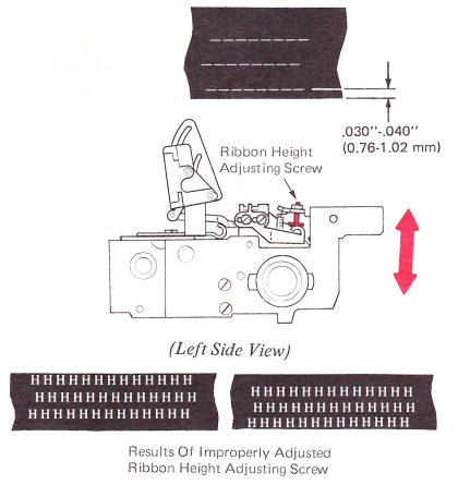
8. Ribbon Lift Height — In the film ribbon mode, adjust the ribbon height adjusting screw so the bottom edge of the underscore clears the bottom of the ribbon by .030”-.040” (0.76-1.02 mm). Ribbon spread must be checked after making this adjustment.
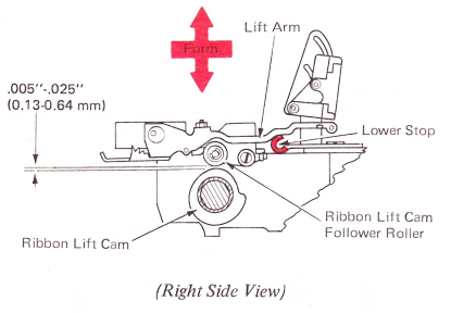
9. Ribbon Lift Arm Lower Stop — Form the left ribbon lift arm lower stop so the ribbon lift cam follower roller clears the ribbon lift cam by .005”-.025” (0.13-0.64 mm) at rest. This ensures free left-to-right movement of the roller.
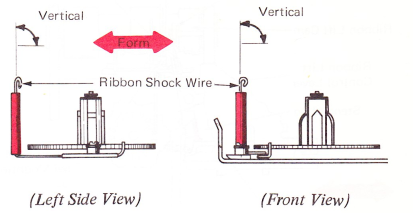
10. Ribbon Shock Wire — Form the shock wire to be vertical front to rear and left to right. This adjustment may need to be readjusted for proper ribbon tracking through the left ribbon lift guide.
11. Stencil Adjustment — Form the stencil lug on the ribbon lift control lever to meet two conditions when the stencil lever is latched in the stencil position.
a. The ribbon feed lockout lug must engage the ribbon feed pawl mounting stud by approximately the thickness of the lockout lug.
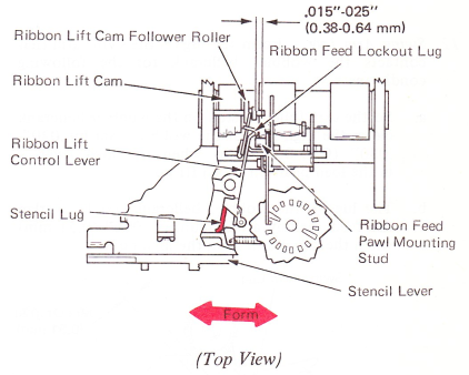
b. The ribbon lift cam follower roller must be moved to the right, completely off the ribbon lift cam, and have .015”-.025” (0.38-0.64 mm) clearance between the roller and the “C” clip at the end of its shaft.
NOTE: During normal typing, in the low lift ribbon position, the ribbon feed lockout lug on the ribbon lift control lever must clear the ribbon feed pawl mounting stud. If necessary, form the ribbon feed lockout lug to get this condition. If the lug is formed, recheck the stencil adjustments.
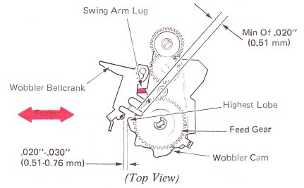
12. Swing Arm Lug — Form the lug on the swing arm that contacts the wobbler bellcrank for the following conditions:
a. So the cam follower stud on the wobbler bellcrank clears the high side of the wobbler cam by .020”-.030” (0.51-0.76 mm) when the load lever is in the load position (Tech III position).
b. The lug on the wobbler bellcrank should overlap the feed gear by a minimum of .020” (0.51 mm) when the swing arm is on the high point.
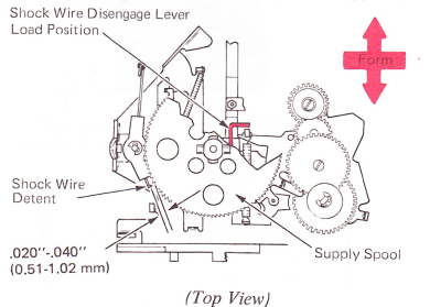
13. Shock Wire Disengage Lever (Load Position) — Form the right-hand arm on the shock wire disengage lever so the shock wire detent clears the ribbon supply spool by .020”-.040” (0.51-1.02 mm) when the load lever is in the load position. Ensure that the wobbler eccentric lug cannot get under the arm. If necessary, form the
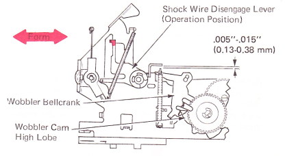
14. Shock Wire Disengage Lever (Type Position) — In the IBM Tech III ribbon mode, form the shock wire disengage lever rest position lug so the shock wire disengage lever arm clears the wobbler eccentric by .005”-.015” (0.13-0.38 mm) when the wobbler bellcrank is on the high point of the wobbler cam.
15. Cartridge Guides — Form the cartridge guides to center the ribbon take-up and supply cores within the holes in the top of the cartridge. Maintain .005”-010” (0.13-0.25 mm) end play of the cartridge.
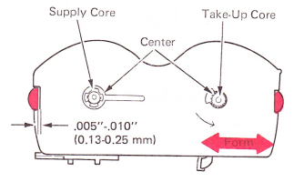
16. Cartridge Retaining Springs — Center the cartridge retaining springs in the holes in the cartridge guide lugs. Adjust the springs left to right so they positively hold the IBM Tech III ribbon cartridge down against the ribbon feed plate. Refine the right spring so the takeup core interlock clears the center surface of the take-up post by .005”-.020” (0.13-0.51 mm).
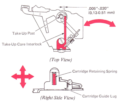
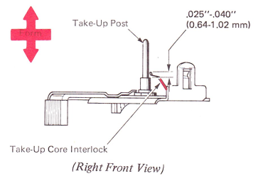
17. Take-Up Core Interlock — Form the take-up core interlock so that in the load position, the tip of the interlock is .025”-.040” (0.64-1.02mm) above the top edge of the center step on the take-up post.
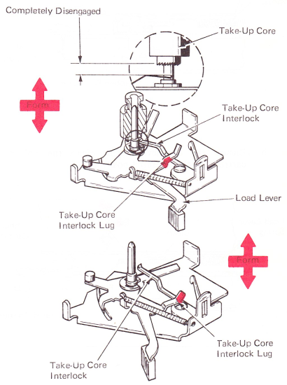
18. Load Lever — Form the take-up core interlock lug on the load lever to meet two conditions.
a. In the operate position, it must hold the take-up core interlock down completely disengaged from the take-up core.
b. When going from load to operate, the tip of the lug must clear the top surface of the take-up core interlock by enough to reliably depress it.
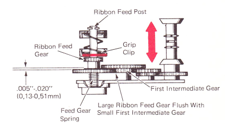
19. Made Button Grip Clip — Adjust the ribbon mode button grip clip up or down on the ribbon feed post to get .005”-.020” (0.13-0.51 mm) clearance between the lower feed gear and the first intermediate gear (with the mechanism in the film ribbon mode). The bottom of the large ribbon feed gear should be flush with the bottom of the small first intermediate gear.
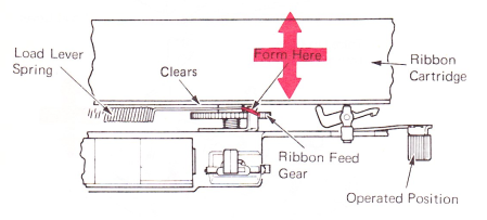
20. Load Lever Spring — Form the load lever spring to meet the following conditions:
a. Ensure the load lever spring clears the ribbon feed gear with a minimum of .005” (0.13 mm) in the ribbon load position.
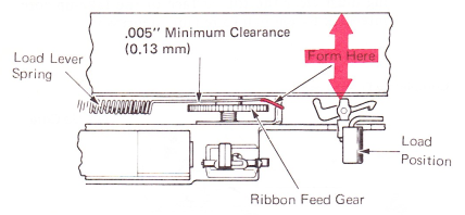
b. Ensure the load lever spring clears the ribbon cartridge in the operated position.