Selectric Resources
"CORRECTING" MECHANISM OPERATIONAL THEORY
The purpose of the correcting mechanism is to correct original copy errors from the keyboard. A correcting tape supply spool is mounted at the left rear corner of the ribbon plate and a tape take-up spool is mounted at the right rear corner of the ribbon plate (Figure 1). The correcting tape is guided from the tape supply spool on the left, across the front of the cardholder, to the tape take-up spool on the right.
To correct an error, the operator depresses the correcting key and then strikes the incorrect character. As the operator strikes the incorrect character, the correcting tape is lifted between the ribbon and the paper. The impact of the typehead causes the correcting tape to‘either cover up the character or lift it off of the paper, depending upon which supplies are used. No escapement occurs during this correcting cycle. Since the carrier is still positioned at the point where the error was committed, the operator can type the correct character and resume normal typing.
Each of the correcting tapes is designed to be used with a specific IBM ribbon. The IBM Tech III Cover-up Tape is used with the IBM Tech III Ribbon. (Both are color coded blue.) The Lift-off Tape is used with the IBM High Yield Correctable Film Ribbon. (Both are color coded orange.)
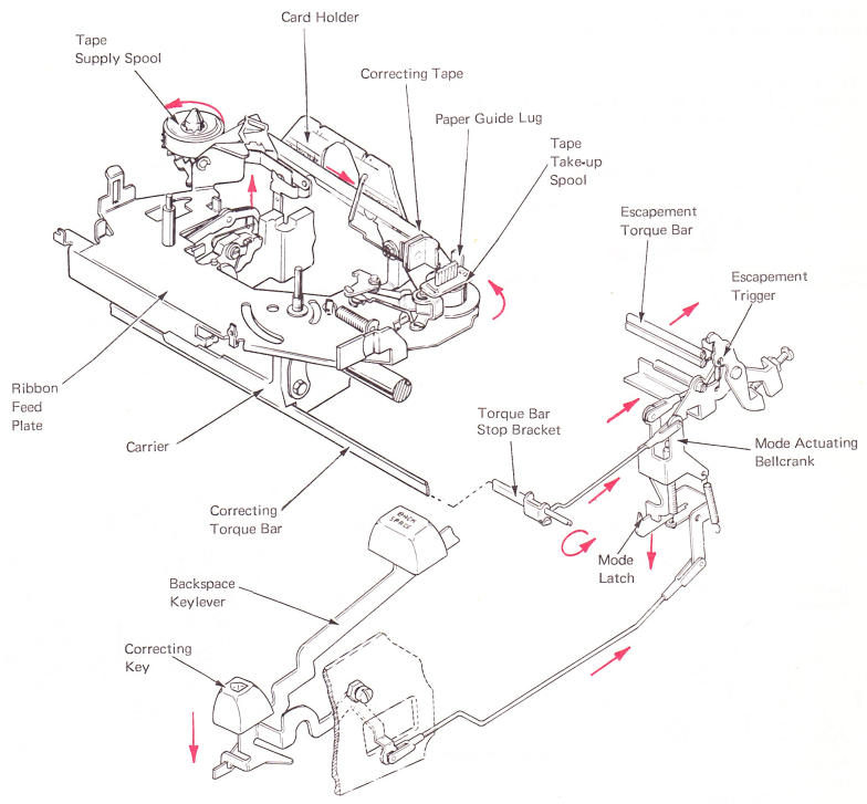
Figure 1 — Correcting Mechanism
CORRECTING MECHANISM LEVELS
Level 1 (PRE-FTB) — This mechanism has the correcting torque bar mounted on the left in a hole in the machine power frame and is known as a pre-floating torque bar (PRE-FTB).
Level 2 (FTB) — This mechanism has the correcting torque bar mounted in brackets that are attached to the front carrier support at both ends. The left bracket has a slot so the torque bar can slide (float) front to rear. This front-to-rear motion helps eliminate binds between the carrier and the torque bar as the carrier moves left to right on the writing line. This is known as the floating torque bar (FTB) mechanism.
CORRECTING TORQUE BAR OPERATION
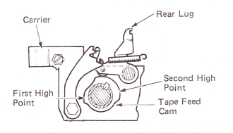
The correcting torque bar extends across the machine just to the rear of the front carrier support (Figure 2). Its purpose is to activate tape lift and tape feed with the carrier in any position across the writing line.
The correcting keylever performs two operations. First, an actuating lug contacts the front of the backspace keylever which operates the backspace mechanism (see backspace section). Second, the correcting keylever releases the mode actuating bellcrank which will operate the correcting torque bar.
NOTE: Complete operational theory of the backspace mechanism is covered in the “Backspace” section of the “Selectric” Typewriter Service Manual.
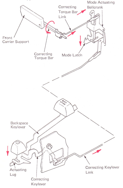
Figure 2 — Correcting Torque Bar Operation
As the correcting keylever is depressed, it moves the correcting keylever link to the rear. The link rotates the mode latch down. Rotating the latch releases the mode actuating bellcrank, allowing it to pivot top to rear under spring load. A correcting torque bar link extends from the bellcrank forward to the correcting torque bar and pivots it bottom to rear. The rotation of this torque bar activates tape lift and tape feed.
CORRECTING TAPE LIFT
The tape lift mechanism is located on the left side of the carrier (Figure 3). As the correcting torque bar is rotated to its actuated position, it pivots the tape lift actuating arm top to front which slides the lift arm and latch assembly forward. This positions the lift latch above the lift cam follower.
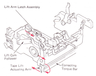
Figure 3 — Lift Arm And Latch (Left Side View)
When the print sleeve rotates, the tape lift cam raises the tape lift cam follower which raises the lift arm and latch assembly (Figure 4). As the lift arm and latch assembly is raised, an extension on the rear of it will raise the tape lift assembly. An arm on the tape lift assembly engages the tape supply cradle fork on the tape supply cradle assembly. As the tape lift assembly raises, the cradle assembly is tilted to maintain tape alignment and prevent folding of the correcting tape.
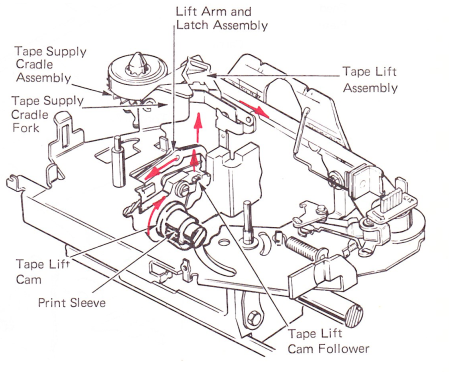
Figure 4 — Tape Lift Operation
CORRECTING TAPE FEED
The correcting tape feed mechanism is located on the right side of the carrier (Figure 5). It is designed so that the correcting tape is fed in two parts. One-third is fed before print and two-thirds is fed after print. This is done by a tape feed cam with two high points, the second high point supplying two times as much motion as the first. The first one-third is to remove slack in the tape before the correction operation. This prevents the tape from sticking to the paper. The second feed operation is to advance the tape.
(Figure 5 — FTB Right Side View)
The FTB feed mechanism is activated by the correcting torque bar (Figure 6) moving the top of the, tape lift actuating arm to the front. The lift actuating arm pushes the inhibitor actuation bellcrank, which rotates the top of the tape feed inhibitor out of the path of the tape feed cam follower.
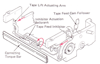
Figure 6 — Tape Feed At Rest
The PRE-FTB feed mechanism is activated by the operation of the correcting torque bar in the same way as the tape lift mechanism. The torque bar rotates the step on the tape feed inhibitor out of the path of the tape feed cam follower (Figure 7).
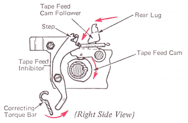
Figure 7 — Pre-FTB Tape Feed At Rest
As a print operation occurs and the tape feed cam rotates (Figure 8), the tape feed cam follower is allowed to follow the shape of the tape feed cam from its highest point toward its low point. The rear lug on the follower moves forward allowing the spring loaded tape feed pawl to rotate counterclockwise by means of a feed bellcrank and feed link, engaging the window in the spiked wheel.
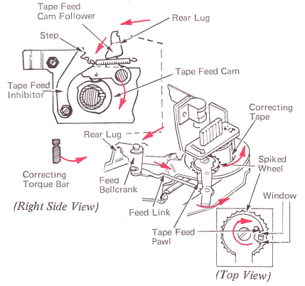
Figure 8 — Tape Feed Inhibitor
The tape feed cam then rotates to its first high point. The tape feed pawl by means of the cam follower, feed bellcrank and link rotates the spiked wheel clockwise for the first one-third tape feed (Figure 9). The feed cam then rotates to the low point again. The follower is prevented from contacting the cam on its low point by the inhibitor. The inhibitor prevents placing the heavy cam follower spring load on the cam during print which occurs at this time. The cam then begins its rise to the second high point and the cam follower causes the correcting tape to be fed the remaining two-thirds of the tape feed.
The spiked wheel which is mounted on the tape feed swing arm is heavily spring loaded toward the tape take-up spool. This causes the spikes on the wheel to engage the used tape. As the spiked wheel rotates, it causes the take-up spool to rotate. pulling new tape into the print position and winding up the used tape.

Figure 9 — Tape Feed Operation
TAPE BIAS (CONTROL) SYSTEM
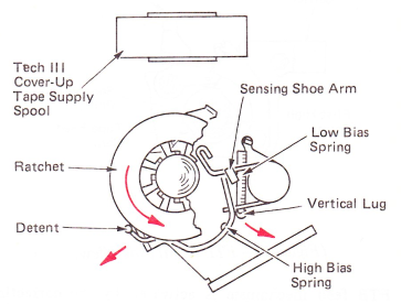
The correcting tape supply cradle assembly contains a bias system that performs three functions. First, the detent on the high bias spring prevents' the supply spool from being rotated clockwise (Figure 10).
Second, a low bias is supplied for use with the IBM Tech III Cover-up Tape. This bias is produced by a low bias spring. As tape is being pulled off the supply spool and the tape supply spool ratchet turns counterclockwise, the detent on the high bias spring is moved over a tooth on the ratchet. The other end of the high bias spring, which contacts a vertical lug on the sensing shoe arm, pivots the arm. The low bias spring connected to the vertical lug on the sensing shoe arm produces the low bias.
(Top View)
Figure 10 — Low Bias Operation
Finally, high bias is developed for use with the Lift-off Tape. As the detent on the high bias spring moves over a tooth on the ratchet, high bias is developed due to lugs on the bottom of the lift-off tape supply spool preventing the sensing shoe from rotating inward (Figure 11). This causes the high bias spring to flex, producing the high bias. One lug on the bottom of the Lift-off Tape supply spool has been shortened. This allows the spool to bottom completely on the supply spool ratchet if the sensing shoe is under a window in the ratchet while the operator is loading the tape.
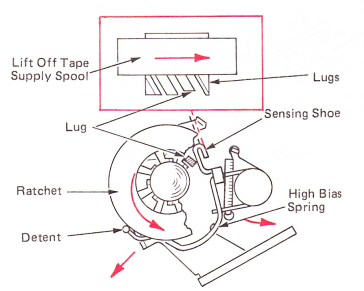
Figure 11 — High Bias Operation (Top View)
ESCAPEMENT TRIGGER OPERATION
The escapement trigger is disengaged from the escapement torque bar to prevent escapement during a correcting cycle. Disengagement of the trigger is done from the mode actuating bellcrank through the trigger link (Figure 12). As the bellcrank rotates to its activated position, the escapement trigger is rotated top to rear out of engagement with the torque bar. It is held in this disengaged position by the spring tension on the mode actuating bellcrank until the trigger lever is operated either through a print or spacebar operation.
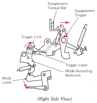
Figure 12 — Escapement Trigger Disengaged
The next time a print or spacebar cycle is started the trigger will not contact the escapement torque bar and no escapement operation will result (Figure 13). As the trigger is pulled down during this cycle a forward extension of the trigger lever will contact the mode actuating bellcrank and rotate it back to its latched position. This restores the complete correcting mechanism to rest.
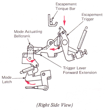
Figure 13 — Escapement TriggerActuated
CORRECTING TAPE LOAD
When the correcting tape needs to be changed, the tape load lever is moved to the right to the load position (Figure 14). The load lever performs three functions to help installation and removal of the tape.
1. A tape guide mounted on the rear of the load lever pivots forward.
2. A separator wire is pivoted top to the front by means of a cam slot in the load lever.
3. The spiked wheel which is mounted on the tape feed swing arm is pivoted forward by 3 lug on the load lever.
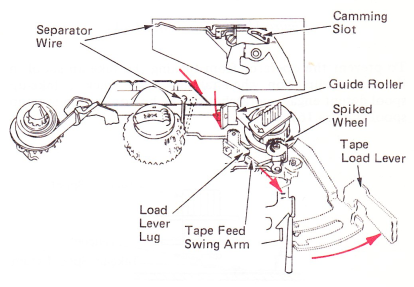
Figure 14 — Tape Load
LOAD INTERLOCKS
A toggle spring holds the tape load lever in either the load or type position (Figure 15A). An extension on the toggle spring engages a hole in the ribbon load lever so it cannot be moved to the load position while the tape load lever is in the load position. When the ribbon load lever is operated (Figure 15B), an extension on the ribbon load lever enters a notch in the tape load lever to prevent operating the tape load lever to the load position.
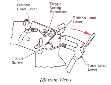
Figure 15A — Ribbon Load Lever Load Position
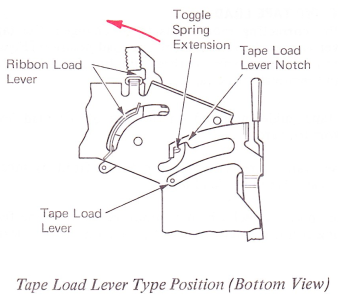
Figure 15 B — Load Interlocks
To prevent the operator from turning the take-up spool in the wrong direction when taking up the slack, a take-up spool detent engages a ratchet on the bottom of the take-up spool (Figure 16).
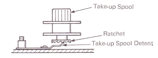
Figure 16 — Take-up Spool Detent