Selectric Resources
ROTARY BACKSPACE (RB/S) OPERATIONAL THEORY
The rotary backspace mechanism pulls the carrier return/backspace cable to move the carrier to the left one space at a time. This mechanism functions with either 10 or 12 pitch machines or on dual pitch machines in either pitch.
Because of this different way of backspacing, the carrier transport system is a little different. The main difference in the transport system is the use of strong steel cable(s) that reduce stretch. The tab/escapement cable or cord is attached in approximately the same manner as the NRB/S tab/escapement cord. The carrier return/backspace cable is attached at the carrier to an arm on the cable anchor bracket. This arm is free to pivot and is heavily spring loaded to the right against a stop lug. The purpose of the pivot arm and spring is to take up the shock when the carrier is pulled to the left by the cable. The other end of the cable is attached to the carrier return/backspace cable drum. The carrier return/backspace cable drum and backspace ratchet are one piece and operate as a unit (Figure 1).
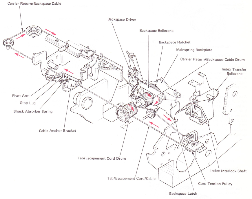
Figure 1 — Rotary Backspace Mechanism (Right Front View)
CABLE TENSION SYSTEM
For proper operation, it is necessary to maintain a constant tension on the transport cables or cords. The cables or cords are wound in opposite directions. The tab/escapement cord drum is attached to the front of the escapement shaft and winds the cord in a counterclockwise direction. The carrier return/backspace cable drum assembly is attached to the back of the escapement shaft and winds the cable in a clockwise direction. The right-hand transport pulley is spring loaded to the right and maintains a constant tension on the transport cable and cord (Figure 2).
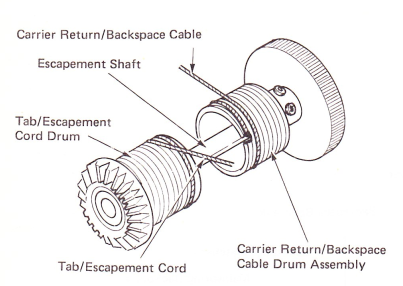
Figure 2 — Level 2 Cable Tension System
LEVEL 1
On level 1 machines, the tab/escapement cable drum is attached to the front of the escapement shaft, but the carrier return/backspace cable drum is free to rotate on the escapement shaft (Figure 3).
A constant pressure is applied to the carrier return/backspace cable drum through the cable tension arm and cable tension spring. The cable tension arm has a “D” shaped mounting hole which fits over a flat on the escapement shaft, which causes it to turn with the shaft. The cable tension spring is attached to a lug on the cable tension arm and an anchor stud on the backspace ratchet, which is permanently attached to the carrier return/backspace cable drum. This spring keeps the transport cables tight.
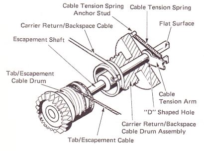
Figure 3 — Level 1 Cable Tension System
ROTARY BACKSPACE OPERATION
Rotary backspace operates from the same single sided operational cam and cam follower as carrier return and index. The spacebar is the only function operated by the double cam.
The operation of the backspace mechanism from the keybutton to the backspace latch is covered in the Operational Control Section of this manual.
Since the backspace ratchet and the carrier return/backspace cable drum are one piece, when the backspace ratchet rotates clockwise (as viewed from the front), the cable drum will also rotate clockwise pulling the carrier return/backspace cable. The motion to rotate the drum is provided by the backspace latch. backspace bellcrank, backspace links and backspace driver. The bellcrank and driver are mounted on studs on the mainspring backplate. The driver mounting hole is a slot (Figure 4).
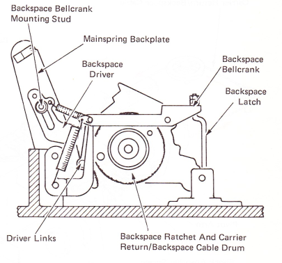
Figure 4 — Rotary BackspaceAt Rest (Front View)
As the latch is pulled down by the cam follower, it pulls down on the right end of the bellcrank, causing the left end to move up. The bellcrank is connected to the driver by the driver links and spring. As the left end of the bellcrank moves up, it pulls up on the driver links. The driver causes it to first pivot or rotate on its mounting stud until it contacts the backspace ratchet (Figure 5).
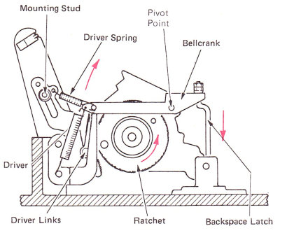
Figure 5 — Driver Engaged In Ratchet
When the backspace driver teeth have bottomed in the teeth of the backspace ratchet, the driver no longer pivots but starts to drive up in its slot, rotating the backspace ratchet (Figure 6).
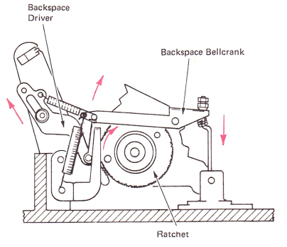
Figure 6 — Rotary Backspace Operated Position (Front View)
On dual pitch machines, the amount of pull on the carrier return/backspace cable must be controlled so that the rotary backspace operates reliably in either 10 or 12 pitch. This is done on dual pitch machines by a pitch cam which is mounted on the backspace driver mounting stud. A stud on the driver rests on top of the cam surface of the pitch cam. The driver stud resting on either the low point or high point of the pitch cam controls the rest position (starting pivot point) of the driver. This determines the point at which the driver engages the backspace ratchet. In the 10 pitch mode, the driver engages the ratchet at a lower point, giving more rotary motion to the ratchet. In the 12 pitch mode, it engages the ratchet at a higher point, giving less motion. The position of the pitch cam is controlled by a cable connected to the switch pitch lever (Figure 7).
The amount of pull on single pitch machines is controlled by the motion adjustment (covered in the adjustment section).
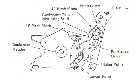
Figure 7 — Rotary Backspace Switch Pitch Operation (Rear View)
INDEX INTERLOCK
Since the rotary backspace mechanism uses the same cam and cam follower as carrier return and index, it is necessary to interlock the index mechanism during a backspace operation. The lower index link is connected at the bottom to the index multiplying lever. It is connected at the top by a stud in a slot in the index transfer bellcrank. The top of the link is spring loaded toward the front, therefore, its rest position is in the front of the slot. When carrier return or index is operated, the top of the link maintains its rest position in the slot and operates the index transfer bellcrank (Figure 8).
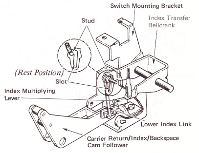
Figure 8 — Index Interlock Normal Index Operation (Right Front View)
The rear motion of the backspace latch is used to operate the index interlock. An index interlock link connects the backspace latch to the index interlock bellcrank. The index interlock bellcrank is attached to the index interlock shaft which pivots in the switch mounting bracket. The end of the index interlock shaft is positioned directly in front of the lower index link. When the backspace latch moves to the rear, the interlock bellcrank moves the top of the lower index link to the rear of the slot. When the backspace is operated, the index multiplying lever is still operated, but the lower index link will move down in the slot and the index transfer bellcrank will remain at rest (Figure 9).
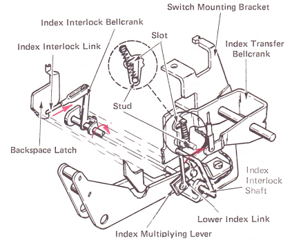
Figure 9 — Index Interlock Backspace Operation (Right Front View) (Level 2)
Level 1 machines have a paddle on the end of the index shaft that is positioned directly in front of the stud on the top of the lower index link (Figure 10).
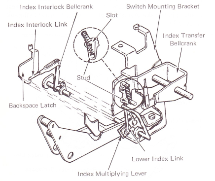
Figure 10 — Index Interlock Backspace Operation (Right Front View) (Level 1)