Selectric Resources
NONROTARY BACKSPACE ADJUSTMENTS
NOTE: All operational control adjustments must be correct before making backspace adjustments.
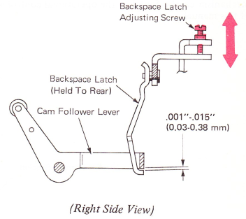
1. Backspace Latch Height — Adjust the backspace latch adjusting screw for .001”-.015” (0.03-0.38 mm) clearance between the latch and the cam follower levers. This adjustment should be made to the low side of the specification to ensure a minimum of lost motion.
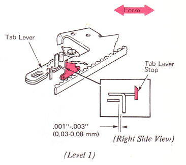
2. Tab Lever Stop — Level 1 — Form the stop front and rear for a clearance of .001”-.003” (0.03-0.08 mm) between the vertical lug on the tab lever and the backspace pawl when the pawl is bottomed in its rack.
NOTE: Make sure all escapement bracket and print escapement adjustments are correct before forming this stop.
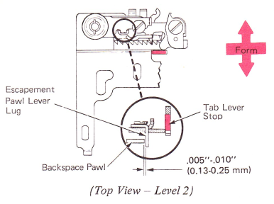
Level 2 — Form the stop front and rear for a clearance of .005”-.010” (O.13-0.25 mm) between the vertical lug on the escapement pawl lever and the backspace pawl when the pawl is bottomed in its rack.
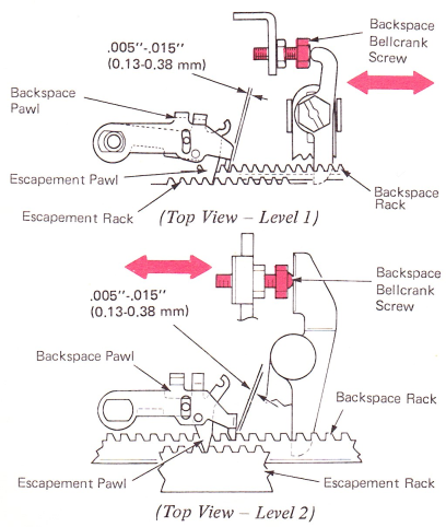
3. Backspace Rack — With the machine at rest, adjust the backspace bellcrank screw in or out to get .005”-.015” (0.13-0.38 mm) clearance between the working surface of a rack tooth and the backspace pawl. Check at both ends of the writing line.
This adjustment keeps lost motion to a minimum and ensures that the backspace pawl will positively reset in the next rack tooth at the completion of a backspace operation.
No clearance can cause escapement problems as well as backspace problems by allowing the backspace pawl, instead of the escapement pawl, to hold the carrier.
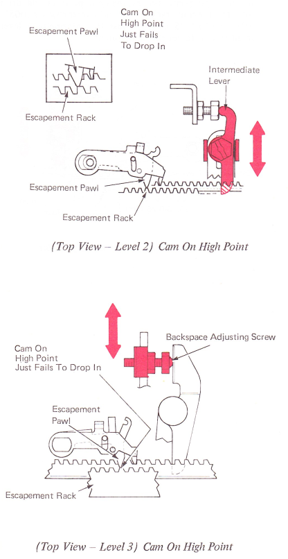
4. Backspace Motion — This adjustment is gotten by adjusting the intermediate lever front-to-rear. Any time this adjustment is changed, the backspace rack adjustment should be checked and readjusted if necessary. Moving the lever to the rear increases backspace rack motion.
Level 1 — With the backspace cam manually operated to the high point, the escapement pawl should drop into the previous rack tooth and overthrow by .005”-.010” (0.13-0.25 mm). Adjust the intermediate lever front-to-rear to get this adjustment.

Levels 2 And 3 — Adjust the intermediate lever on level 2 and the backspace adjusting screw on level 3 so that a backspace operation just fails under hand operation. During a powered backspace operation, the carrier develops enough motion for a positive operation. Too much motion will cause double or space-and-a-half backspacing.