Selectric Resources
ROTARY BACKSPACE ADJUSTMENTS
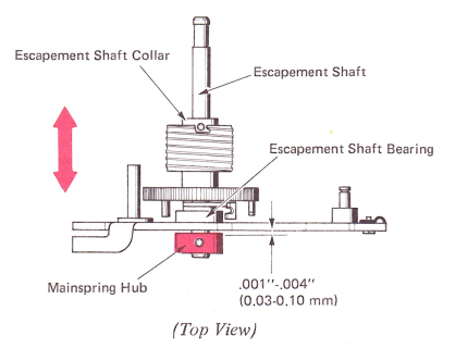
1. Mainspring Hub — Adjust the mainspring hub for .001”-.004” (0.03-0.10 mm) end play of the escapement shaft in the rear escapement bearing. This adjustment should be made with the escapement shaft collar loose.
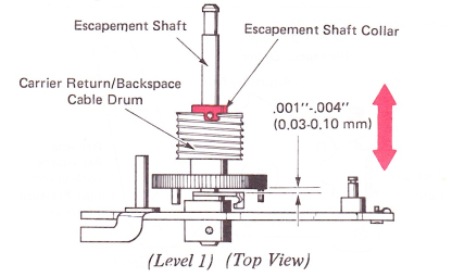
2. Escapement Shaft Collar — Level 1 — Adjust the escapement shaft collar for minimum end play with no binds of the carrier return/backspace cable drum on the escapement shaft.
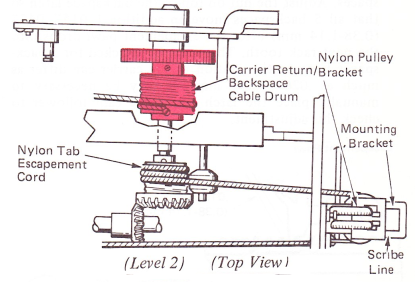
Level 2 — With the escapement shaft end play removed toward the front of the machine, adjust the carrier return/backspace cable drum on the shaft for minimum end play no binds.

3. Transport Cable Tension —
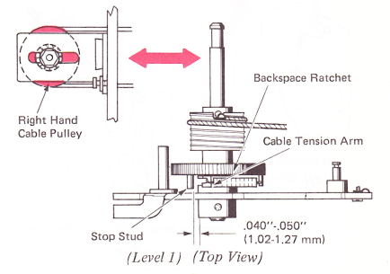
Level 1 — On all steel transport machines, adjust the right-hand cable pulley left or right so the cable tension arm clears the stop stud on the backspace ratchet by .040”-.050” (1.02-1.27 mm).
NOTE: If the right-hand cable pulley reaches either end of the adjustment slot, the tab/escapement cable drum must be repositioned on the escapement shaft.
Level 2 — On dual transport equipped machines (nylon tab/escapement cord), adjust the carrier return/backspace cable drum so the nylon pulley bracket aligns with the line on the mounting bracket.
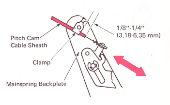
4. Pitch Cam Cable Cover (Dual Pitch Only) — The pitch cam cable cover should extend 1/8”-1/4” (3.18-6.35 mm) beyond the clamp on the mainspring backplate.
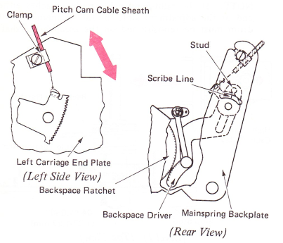
5. Pitch Cam (Dual Pitch) — In the 12 pitch mode, hand cycle the backspace until the driver just bottoms in the ratchet. Adjust the pitch cam cable cover on the left carriage end plate so the line on the pitch cam lines up with the center of the stud on top of the backspace driver. Observe this condition through the hole in the backplate.
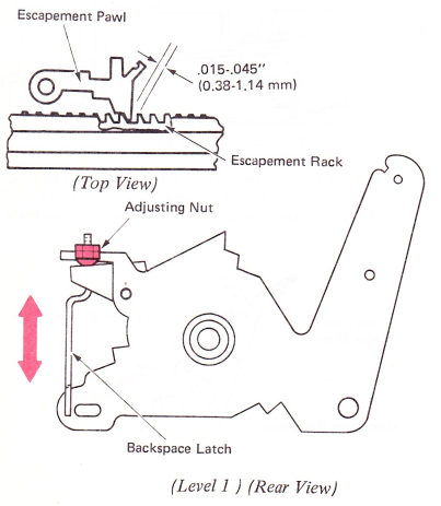
6. Backspace Motion — Level 1 — Place dual pitch machines in the 10 pitch mode. Position the carrier approximately in the center of the writing line. Hand cycle 5 backspaces. Adjust the nut on top of the backspace latch so that all 5 backspaces move an additional .015”-.045” (0.38-1.14 mm) after the escapement pawl drops into the next rack tooth. This must be checked for 5 backspaces because the motion at the carrier can differ as much as .020” (0.51 mm). It may be necessary to manually place the latch below the cam follower to check this adjustment.
Level 2 —
NOTE: On dual pitch machines, the pitch cam adjustment must be properly adjusted in the 12 pitch mode before making this adjustment.
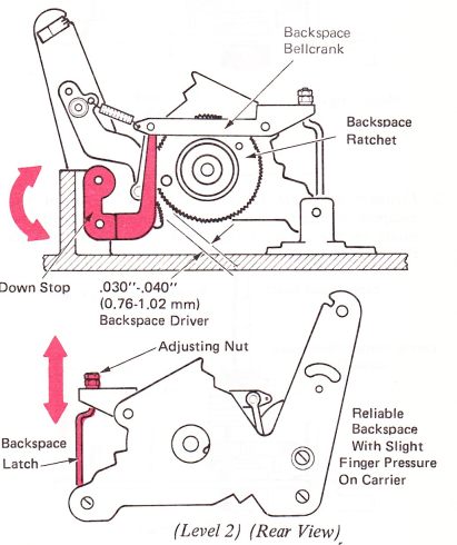
a. Adjust the downstop for a .030”-.040” (0.76-1.02 mm) clearance between the driver and ratchet. If the machine is dual pitch, it must be in the 10 pitch mode.
CAUTION: Be sure the bellcrank does not slip behind the downstop as it restores to rest. Form stop if necessary.
b. Adjust the backspace latch for reliable backspacing under power with a slight finger pressure on top of the carrier.
CAUTION: If latch does not go under the bail, make the adjustment again.
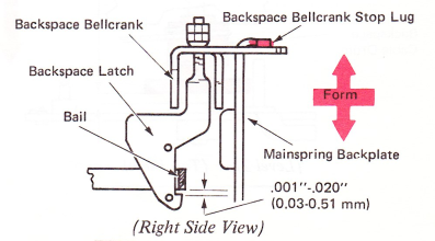
7. Backspace Latch Height — Form the backspace bellcrank stop lug on the mainspring backplate for .001”-.020” (0.03-0.51 mm) backspace latch clearance under the bail. After making this adjustment, check for some clearance between the backspace driver and the backspace ratchet with all parts at rest. If no clearance exists, readjust the backspace motion and the backspace latch height adjustments.
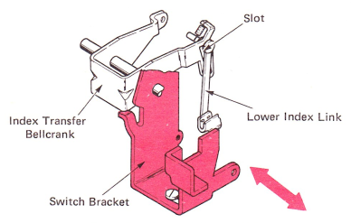
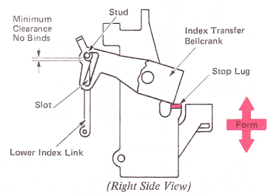
8. Switch Bracket — Adjust the switch bracket left or right to ensure that the lower index link does not bind in the slot in the index transfer bellcrank.
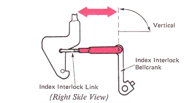
9. Index Interlock Link — Adjust the index interlock link so the index interlock bellcrank arm is vertical.
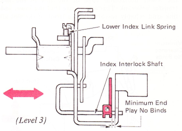
10. Index Interlock Shaft (Levels 1 And 2) — Adjust the index interlock shaft left or right so the paddle clears the lower index link spring by .001”-.010” (0.03-0.25 mm). Check for interference with the escapement trigger upstop. Maintain minimum end play with no binds.
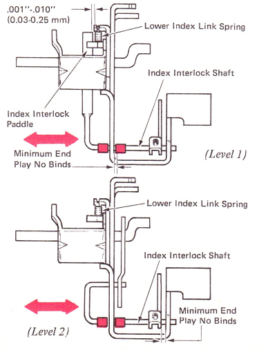
Level 3 — Adjust the index interlock shaft bellcrank left or right to get minimum end play, no binds between the switch bracket and the bellcrank.
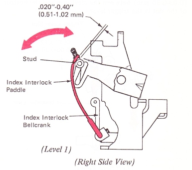
11. Index Interlock Paddle (Level 1) — Loosen the setscrew on the index interlock bellcrank. Adjust the paddle front-to-rear for .020"-.040”(0.51-1.02 mm) clearance to the stud on the lower index link. Position the bellcrank left or right to ensure the interlock link does not bind in the backspace latch or at the clevis.
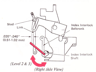
Levels 2 And 3 — Adjust the index interlock shaft front to rear for .020”-.040” (0.51-1.02 mm) clearance to the link on the index transfer bellcrank.
12. Index Transfer Bellcrank Stop Lug — Form the index transfer bellcrank stop lug for minimum clearance with no binds between the stud on the lower index link and the lower horizontal edge of the slot in the index transfer bellcrank. This will ensure that the lower index link stud reliably restores to the front of the slot after a backspace operation.
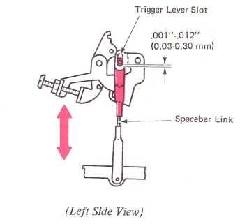
13. Spacebar Link — With the escapement trip link properly adjusted, adjust the spacebar link for .001"-.012” (0.03-0.30 mm) between the clevis pin and the bottom of the slot in the trigger lever.
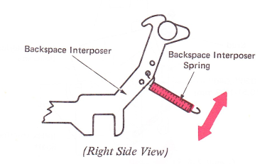
14. Backspace Interposer Spring — The backspace interposer spring must be in the center hole in the interposer.