Selectric Resources
PRINT ADJUSTMENTS
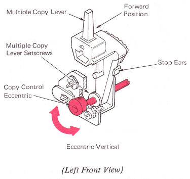
1. Copy Control Lever — Loosen the multiple copy lever setscrews and rotate the shaft until the high point of the eccentric is up when the multiple copy lever is in the forward detent position. The stop extensions on the copy control detent spring should be formed to provide a positive detent in the far front and rear positions of the lever.
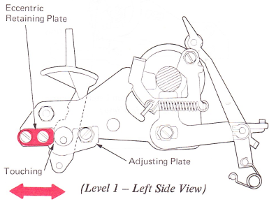
2. Platen Adjusting Plates — Adjust the eccentric retaining plates front to rear on level 1 machines, or the copy control eccentric left to right on level 2 machines so there is no front-to-rear motion and no binds exist between the eccentric and the platen adjusting plates on each side of the machine.
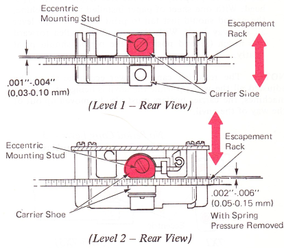
3. Carrier Shoe — Adjust the level 1 carrier shoe eccentric mounting stud to get .001”-.004” (0.03-0.10 mm) vertical play between the carrier shoes and the escapement rack. The level 2 carriers equipped with the spring loaded carrier shoe should be adjusted for .002”-.006” (.005-0.15 mm) of vertical movement with the spring pressure removed. This adjustment should be checked at several points along the escapement rack.
Level 3 Parallel — Loosen mounting screw on carrier shoe. Press down firmly on rear of carrier, keeping carrier shoe parallel with escapement rack; tighten screw.
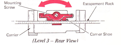
NOTE: On RB/S machines, ensure that the escapement pawl is centered in the escapement rack teeth.
NOTE: Adjustments 5 through 8 are for level 1 machines only.
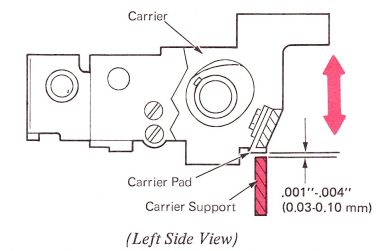
4. Carrier Support — Dual Impression — Adjust both ends of the carrier support vertically to get .001”-.004” (0.03-0.10 mm) clearance with the bottom of the carrier pad across the whole length of the writing line. The support is attached to the machine power frame by a binding screw at each end.
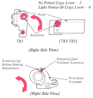
5. Anvil (Level 1) — Adjust the eccentric at each end of the anvil to properly limit the free flight of the typehead. With one sheet of paper installed in the machine, the period should just fail to print with the copy lever all the way back. With the copy lever pulled forward one notch (second position), the period should print lightly.
NOTE: The restoring cam follower eccentric should be adjusted all the way up while the anvil is being set. On 7X5 machines, the carrier buffers must also‘be moved up out of the way of the anvil.
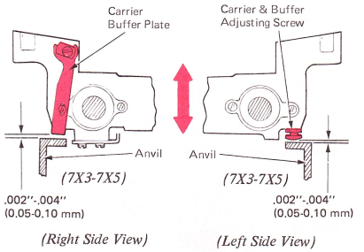
6. Carrier Buffers (Level 1 Only) (7X3-7X5) — Adjust the buffer plate attached to the right side of the carrier, and the adjusting screw under the left side of the carrier so that each has .002”-.004” (0.05-0.10 mm) clearance with the top of the anvil.
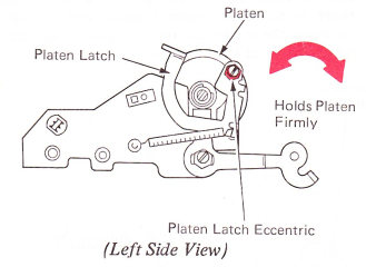
7. Platen Latches — Adjust the platen latch eccentrics, with the high side down, so the platen is held tightly in position vertically and horizontally. The latches should latch and unlatch freely with the feed rolls released.
8. Platen Position —
NOTE: To properly adjust the print mechanism, the correct position of the platen must be established first and then the print adjustments made relative to the platen position.
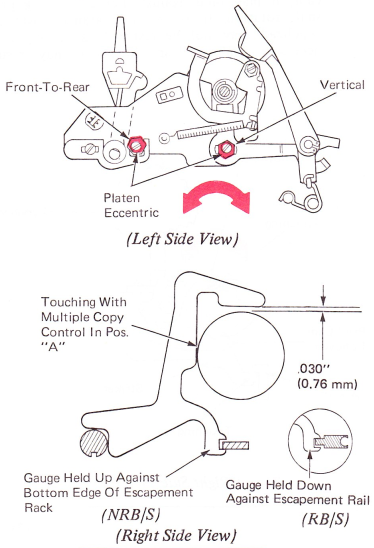
With the copy control lever forward and the print shaft keyway down, loosen the platen eccentrics and move the platen to the far rear, and as low as possible. Insert the platen gauge on the print shaft and escapement rack at one end of the machine.
a. Adjust the platen front to rear until the platen just touches the platen gauge.
b. Adjust the platen height so that the platen clears the gauge by .030” (0.76 mm). Move the gauge to the opposite end of the machine and repeat the procedure. Check for a parallel condition by sliding the gauge back to the beginning end. With the gauge removed, the platen height adjustment should now be readjusted for even top and bottom color of printed characters.
CAUTION: Any change in the front-to-rear position of the platen requires a readjustment of the velocity control plate and anvil on early level machines. Also, any change in the platen position may change the paper feed adjustments. All paper feed adjustments should be checked and readjusted if necessary.
NOTE: On NRB/S machines, the rear of the platen gauge must be held up against the bottom of the escapement rack. On RB/S machines, the platen gauge must be held down against the escapement rail while making this adjustment.
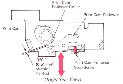
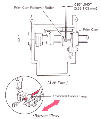
9. Print Cam Follower Stop Screw — Adjust the print cam follower stop screw so the print cam follower roller clears the print cam by .020” (0.51 mm) when the machine is at rest. This clearance allows the roller to shift from one side to the other without touching the cam.
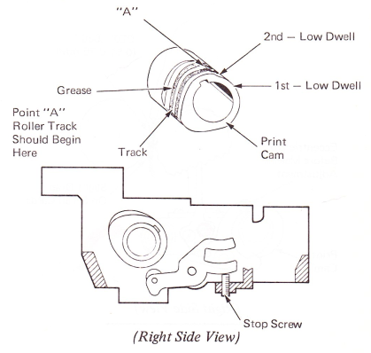
This adjustment may be checked by applying a light film of grease on the print cam and then observing the track that the roller makes in the grease when the machine is hand cycled. If the stop screw has been adjusted properly, the roller track in the grease should begin at point A on the print cam. This is just before the beginning of the rise on the print cam.
If the roller track begins before point A, the roller is adjusted too close to the print cam when the machine is at rest. Incorrect roller-to-cam clearance may cause the roller to drag on the print cam as it shifts during a low velocity selection. The roller may then fail to shift, or shift incorrectly. Also, if the roller is adjusted too close to the cam at rest, it may bounce from the print cam as it tries to follow the print cam. This will cause excessive noise and wear, and will affect the typehead impact velocity.
If the roller track begins after point A, the roller rests too far away from the low spot of the print cam and a loss of typehead velocity may result.
NOTE: Adjustments 11 through 21 are for dual impression machines only.
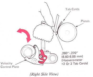
10. Velocity Control Plate (Level 1) — The velocity control plate must be adjusted to satisfy the following two conditions.
a. With the cam follower held lightly against the low point of the print cam, the center of the home character should clear the platen by .260”-.270” (6.60-6.85 mm).
NOTE: The adjustments should be checked with the ribbon removed. The .260”-.270” (6.60-6.85 mm) can be checked with two or three tab cards plus the foot of the Hooverometer handle.
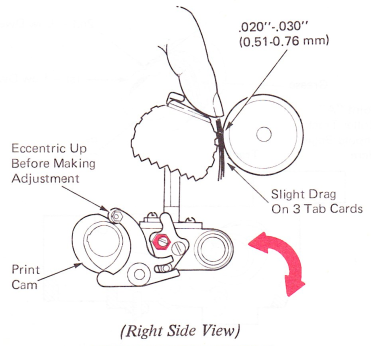
b. With the cam follower held lightly against the high point of the print cam, the home character should clear the platen by .020”-.030” (0.51-0.76 mm). Be sure the anvil does not limit the rocker motion.
11. Print Cam Follower (Level 1) — The print cam follower must be adjusted to satisfy the following conditions:
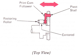
a. Print Cam Follower Stud — Adjust the pivot stud left to right so the rubber roller on the follower is centered on the surface of the restoring cam. The stud is held in place in the carrier casting by a setscrew that may be accessed from the bottom of the machine.
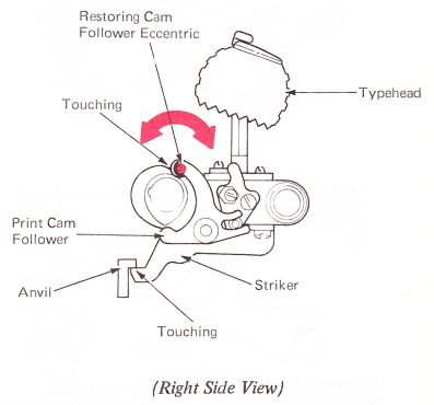
b. Adjust the eccentric, keeping the high point forward,so that the roller just touches the restoring cam when the typehead is held toward the rear. The print cam follower should be on the high point of the cam, and the platen removed to make this adjustment.
NOTE: If the roller is too close to the restoring cam, it may bind against the cam during print shaft rotation. If too much clearance exists, the typehead may not be restored as quickly as is necessary and unclear characters may result.
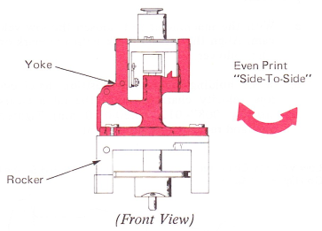
12. Yoke — Position the yoke under its mounting screws so the density of the left and right sides of a printed character is the same.
This adjustment will affect the tilt ring homing adjustment, the typehead homing adjustment and skirt clearance. Be sure to check these adjustments after changing the position of the yoke.
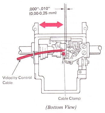
13. Velocity Control Cable Clamp — Adjust the cable cover left to right under the carrier clamp until the end of the cover is flush to .010” (0.25 mm) inside the right hand edge of the cable clamp. This adjustment prevents the yoke actuating lever from binding against the cable cover.
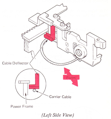
14. Carrier Cable Deflector — Form the deflector to the rear as far as possible without touching the power frame.
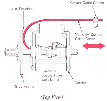
15. Center Cable Clamp — Position the cable cover left to right within the center cable clamp so the bend in the cable will just touch the machine left-hand side frame when the carrier is resting two spaces from the far left-hand margin and will clear the power frame on the third space. This adjustment allows the carrier to operate freely across the whole writing line and allows the velocity control cable to operate with a minimum of bouncing.
16. Velocity Control Keyboard Cable Clamp — Adjust the cable cover front to rear under the clamp so the print cam follower roller will shift on the low velocity side of the print cam by the width of the roller plus .030”-.040” (0.76-1.02 mm) when a low velocity character is half cycled. Moving the cable cover to the rear will produce more motion to the roller.
This adjustment should be checked by observing the track of the roller in the grease on the print cam.
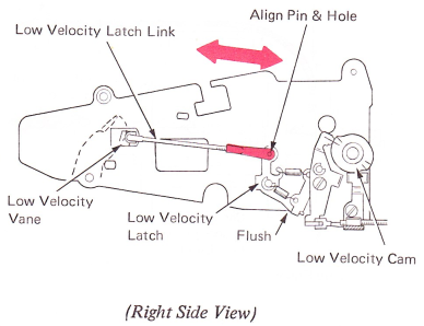
17. Low Velocity Latch Link — With the machine at rest, the low velocity latch link should be adjusted to just reach the distance between the low velocity vane and the low velocity latch. This adjustment ensures the latch will fully overlap the follower, and there will be no lost motion in the system.
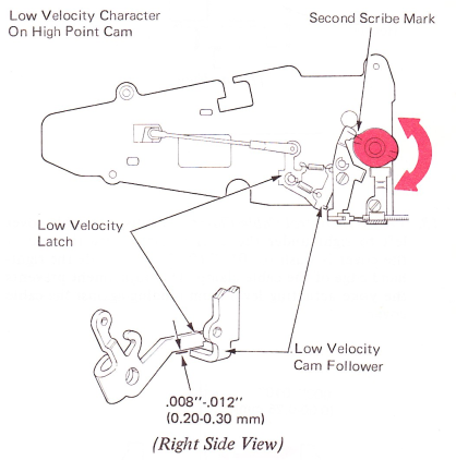
18. Low Velocity Cam — Adjust the cam so that when a low velocity character is slowly hand cycled, the low velocity latch clears the adjusting stop on the cam follower by .008”-.012” (0.20-0.30 mm) just as the cam follower mark lines up with the second mark on the low velocity cam.
This adjustment can easily be made using the following procedure:
a. With the machine at rest, loosen the low velocity cam. Align the second mark with the mark on the cam follower.
b. While holding the cam in position, hand cycle a low velocity character until the latch clears the stop by .008”-.012” (0.20-0.30 mm). Tighten the cam and recheck this adjustment.
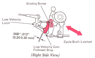
19. Low Velocity Cam Follower Stop — With the cycle shaft latched at rest, adjust the low velocity cam follower stop for .008”-.012” (0.20-0.30 mm) clearance with the low velocity latch. Loosen the binding screw and rotate the low velocity cam follower stop to satisfy this condition.
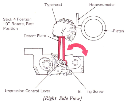
20. Powered Flight — With the machine latched at rest and the impression control lever set at position 4, loosen the binding screw and move the detent plate front-to-rear until a clearance of .250” is obtained between the center of the letter “z” and the platen. The foot of the Hooverometer may be used to measure the clearance.
CAUTION: The copy control lever must be positioned all the way forward when making adjustment No. 20 and No. 21.
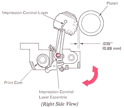
21. Free Flight — With the impression control lever set at 4, hand cycle the letter “z” until the machine is resting on the high point of the print cam. Adjust the eccentric on the impression control lever for .035” (0.89 mm) between the typehead and platen. Keep the high part of the eccentric forward. The pusher end of a springhook may be used to measure this clearance.
NOTE: Adjustments No. 20 and No. 21 directly affect each other and both must be adjusted until they are correct.