Selectric Resources
PIN FEED PLATEN OPERATIONAL THEORY
The purpose of the pin feed platen is to feed continuous forms (Figure 1). This is done by pin wheel assemblies, on each end of the platen which engage holes across the outside edges of the form. Platen cores come in lengths to fit most standard width forms.
During operation, the feed roll release lever should be forward in the released position because the feed rolls are not required to feed the paper.
The platen core is keyed to the right-hand pin wheel body. The pin wheel body is attached by setscrews to a hexagon-shaped platen shaft and rotates with the shaft when the platen is indexed. Each pin wheel body contains 9 pins spaced around its surface. A cam mounts over the hub of the pin wheel and fits into a guide slot in each pin. Mounted on the cam is a control plate which prevents the cam from rotating. The cam control plate is prevented from rotating by an anchor rod. The anchor rod extends the width of the platen and is mounted to each side of the center cover.
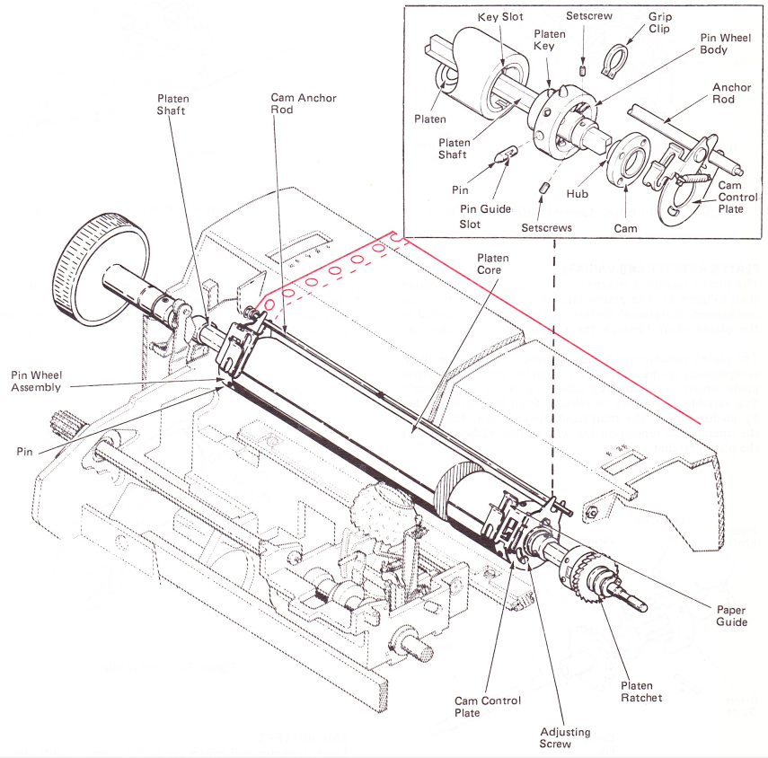
Figure 1 — Pin Feed Platen Assembly
PIN WHEEL OPERATION
As the pin wheel body turns, the pins move around the stationary cam and move in and out of their holes as they pass the high point of the cam. This means that the pins will exit and enter the pin wheel body at an exact position which provides the motion necessary to feed forms through the typewriter (Figure 2). The point at which the pins reach their fully extended position can be changed by adjusting the position of the cam high point.
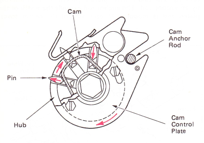
Figure 2 — Pin Wheel Assembly (Right Side View)
PLATEN RATCHET AND VARIABLE
The platen ratchet is attached to the right end of the platen shaft (Figure 3). The platen ratchet is rotated by the index mechanism. Rotational motion of the ratchet is coupled to the platen shaft through the platen variable mechanism.
The platen variable mechanism consists of a variable shaft, compression spring, driver pin, variable driver and a driver guide which is attached by setscrews to the platen shaft. The variable driver may be released from the platen ratchet by pushing in on the right-hand platen knob. This allows the operator to reposition the writing line without moving the platen ratchet.
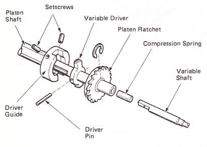
Figure 3 — Platen Ratchet And Variable
PAPER GUIDE
The paper guides are attached to the right and left arm control plates and are positioned in front of the extended pins to guide the paper (Figure 4). The paper guides may be pivoted upward to aid in positioning the form paper around the platen and over the extended pins.
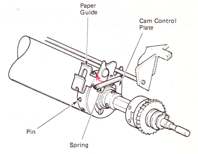
Figure 4 — Paper Guide
CARDHOLDER
The pin feed platen mechanism uses a metal cardholder (Figure 5). The “bridge” area may be removed if it is necessary to prevent contact with the pin wheels on paper guides when the carrier is close to either end of the platen.
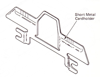
Figure 5 — CardHolder
BAIL ROLLERS
Large diameter bail rollers are available for use with the pin feed platen to aid in keeping the form paper flat against the platen.