Selectric Resources
PIN FEED PLATE ADJUSTMENTS
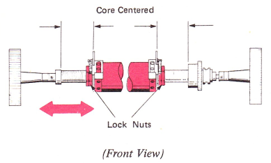
1. Platen Core Lateral Position (Level 1) — Loosen the locknuts on both ends of the platen and center the core. Turn locknuts in and tighten.
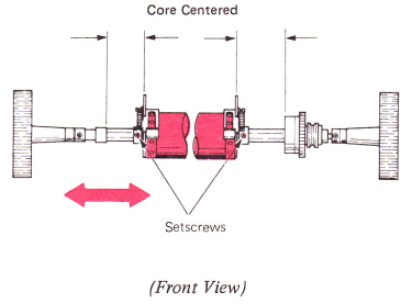
Level 2 — Loosen the setscrews in the pin wheel bodies, center the core and slide the pin wheel assemblies up against each end. Tighten the setscrews.
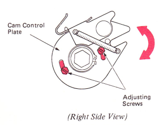
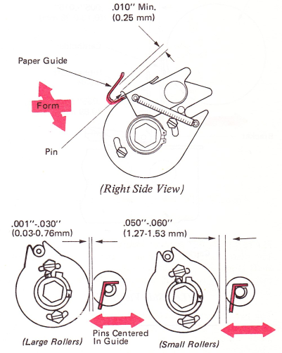
2. Pin Wheel Assembly — Adjust the cam on the control plate so the pins are fully extended immediately after passing into the slot of the form guide.
3. Paper Guide — Form the front extension on the paper guides front to rear for a minimum of .010” (0.25 mm) clearance between the inside bottom of the guide and a fully extended pin as it passes under the guide.
The above condition must exist when the paper bail is resting against the paper guides, and the large paper bail rollers clear the platen by .001”-.030” (0.03-0.76 mm) and the small rollers clear the platen by .050”-.060” (1.27-1.53 mm).
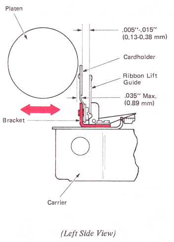
4. Cardholder — Adjust the cardholder for the following conditions:
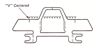
a. Position the cardholder up or down so the bottom of a row of typed “V”s is .002”-.005” (0.05-0.13 mm) above the top edge of the cardholder.
b. Position the cardholder left or right so the bottom of a typed “V” is centered on the vertical marks on the cardholder.
c. Position the cardholder mounting brackets front to rear for a clearance of .005”-.015” (0.13-0.38 mm) between the cardholder and the ribbon lift guides.