Selectric Resources
MOTOR AND DRIVE OPERATIONAL THEORY
The motor and drive mechanism (Figure l) supplies power to drive the cycle shaft and the operational shaft. These two shafts provide the motion through various cams and gears to operate the mechanisms within the “Selectric” Typewriter.
The machine uses a shaded pole motor with a centrifugal clutch to drive the motor pulley. The pulley and drive belt provide drive to the cycle clutch hub, which in turn drives the operational shaft and cycle shaft.
CAPACITOR START MOTOR
Early level machines were equipped with a capacitor start motor. The capacitor gives the motor starting direction and torque. Refer to Early Level Drive this section.
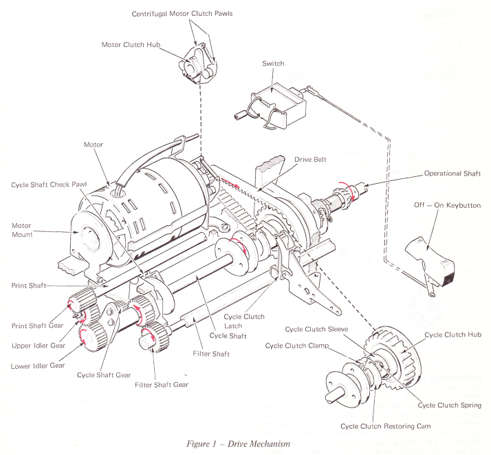
Figure 1 — Drive Mechanism
MOTOR CLUTCH
Due to the low starting torque of the shaded pole motor, a motor pulley clutch (Figure 2) is used. The clutch allows the motor to reach operating speed before it engages the load.
A clutch pulley hub is attached to the shaft of the motor just to the left of the motor pulley. Two clutch pawls pivot on the clutch pulley hub (Figure 2). When the motor is OFF, the pawls are spring loaded against stop lugs on the hub. When the motor is turned ON, centrifugal force causes the clutch pawls to pivot on the hub so the tip of one of the two pawls will engage a tooth on the motor pulley. The pulley will then rotate with the hub and provide drive to the machine.
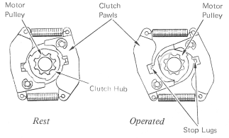
Figure 2 — Motor Clutch (Right Side View)
A plastic bushing is placed on the motor shaft inside the motor pulley (Figure 3). The purpose of the bushing is to keep the motor pulley from sticking to the motor shaft and causing the motor to fail to start.
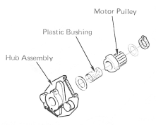
Figure 3 — Motor Pulley
OPERATIONAL SHAFT DRIVE
The cycle clutch pulley is molded to a hub and is continuously rotating within a bronze bearing in the center of the power frame (Figure 4). Two shafts extend into, and are supported by the hub on each side of the cycle clutch pulley. The shaft on the right is called the operational cam shaft. This shaft is in constant rotation with the cycle clutch hub. All powered functional operations are driven by this shaft. The driving connection between the cycle clutch pulley hub and the operational shaft is made by two extensions of the pulley hub that fit into the left side of the torque limiter hub, The level 1 torque limiter hub has two nylon inserts that fit into the torque limiter hub. around the extensions of the cycle clutch pulley hub. These inserts are used to provide a quiet driving connection between the two hubs (Figure 4).
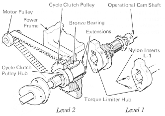
Figure 4 — Operational Cam Shaft Drive Connection
The shaft to the left of the cycle clutch pulley hub is the cycle shaft (Figure 5). The cycle shaft is driven by a spring clutch and only turns when a letter keylever is depressed. The shaft rotates 180 degrees for each character cycle. After 180 degrees rotation, the spring clutch is disengaged and the shaft stops turning.
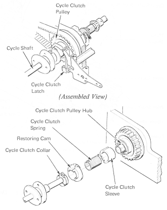
Figure 5 — Cycle Clutch (Exploded View)
CYCLE CLUTCH
The cycle clutch spring provides the driving connection between the cycle clutch pulley and the cycle shaft (Figure 6). Expanding and releasing the spring controls the starting and stopping of the cycle shaft. The left end of the spring fits on the cycle shaft and is attached to the shaft by the cycle clutch sleeve, which is an adjustable clamp. The right end of the spring fits over the driving arbor of the cycle clutch pulley. The inside diameter of the spring is smaller than the driving arbor when the spring is at rest. Therefore, when the arbor turns, top to front, the spring grips the arbor and turns with it. This action causes the spring to turn the cycle shaft also.
The cycle clutch sleeve fits over the right end of the cycle clutch spring. A lug on the right end of the spring is turned up and fits into a notch on the right side of the sleeve. When the cycle clutch sleeve is stopped, the right end of the spring is stopped.
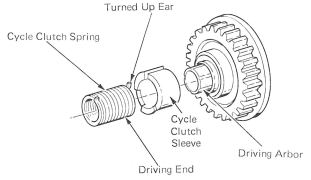
Figure 6 — Cycle Clutch Spring
The cycle clutch sleeve has two latching surfaces 180 degrees apart (Figure 7). As the cycle shaft and clutch spring rotate, one of the latch surfaces will contact the cycle clutch latch after 180 degrees of rotation. This will stop the cycle clutch sleeve.
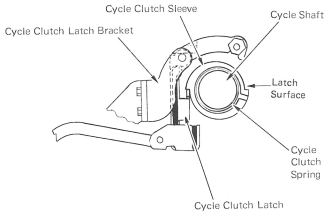
Figure 7— Cycle Clutch Latch (Right Side View)
The cycle shaft will continue turning after the sleeve has been stopped. This continued turning of the shaft causes the left end of the spring clutch to turn, which unwinds or expands the spring. As the spring expands, the driving connection between the hub and the spring is broken. A latching surface is mounted on the left end of the cycle shaft (Figure 8). After the cycle shaft driving connection with the hub is broken and the clutch spring is expanded, the shaft continues rotating until the cycle clutch check pawl engages one of the latch surfaces on the cycle shaft. The clutch spring is then held in an unwound condition and the cycle shaft is at rest.
When another cycle is desired, the cycle clutch latch is pulled free of the sleeve. This will allow the right end of the cycle clutch spring to wind up, contact the hub and go through another cycle. When the step on the opposite side of the sleeve engages the cycle clutch latch, the right end of the spring will be stopped and the cycle shaft will overthrow and the check pawl will drop in. This completes another 180 degree cycle of the cycle shaft.
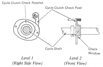
Figure 8 — Cycle Clutch Check Pawl
GEAR TRAIN
The cycle shaft gear (Figure 9) is attached to the end of the cycle shaft and drives the lower and upper idler gears. The idler gears in turn supply motion to the filter shaft and print shaft gears. The filter shaft supplies motion to the keyboard and the print shaft supplies motion to the carrier during each print cycle.
The filter shaft operates the character selection mechanism, the print escapernent mechanism, the shift interlock and a spacebar interlock. The print shaft operates the print mechanism, fine alignment mechanism, and the ribbon feed and lift mechanisms.
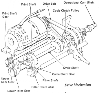
Figure 9 - Gear Train
MOTOR
The motor used in the “Selectric” Typewriter is a 3” shaded pole, induction type motor that normally requires 115 volts, 60 Hz, The motor is mounted at the left rear of the machine with the pulley toward the right. Rubber motor mounts in adjustable brackets support the motor at each end (Figure 10).
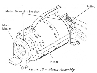
Figure 10 - Motor Assembly
MOTOR WIRING
On grounded 3-wire machines, grounding wires must be connected as shown. On 2-wire machines with capacitor motors, the capacitor must be insulated from the machine frame. Early level machines have a single pole switch (Figure 11).
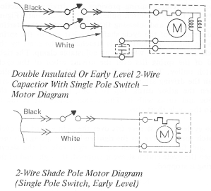
Figure 11 - Wiring Diagrams
WORLD TRADE DIAGRAMS SHOWN IN FIGURE 12 & 13
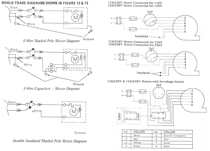
Figure 12 - W.T. Wiring Diagrams
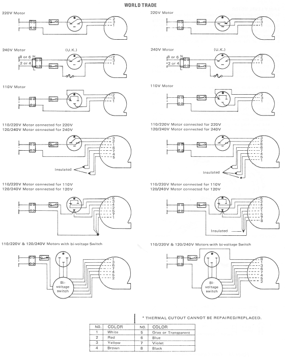
Figure 13 - W.T. Wiring Diagrams
EARLY LEVEL MOTOR
In the early level machines, a capacitor type motor is used. A capacitor, in the start winding circuit, provides a starting torque for the motor and controls the direction of rotation. The capacitor also remains in the circuit while the motor is running. The capacitor is mounted in a vertical position by a bracket at the rear corner of the machine (Figure 14).
In ungrounded systems, the capacitor is isolated from the power frame by an insulator and nylon mounting screws. The motor is insulated from the power frame by the rubber mounting. To change an ungrounded system to a grounded one, three steps must be taken:
1. The two-wire line cord must be replaced with a three-wire cord and the ground lead must be attached to the power frame at the cord clip.
2. A short jumper wire must be connected from the motor to the power frame.
3. The capacitor must be grounded to the power frame by replacing the nylon mounting screws with metal screws and removing the insulating material from between the capacitor and the frame of the machine.
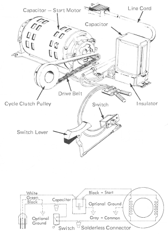
Figure 14 - Early Capacitor Motor