Selectric Resources
MARGINS AND LINELOCK OPERATIONAL THEORY
The purpose of the margin mechanism is to allow the operator to change the length of the writing line. This is done by two margin stops and a margin rack (Figure 1). The left and right margins are determined by the position of the margin stops on the margin rack. The left margin stop is used to limit carrier movement to the left.
The right margin stop first operates a warning bell which signals the operator when the carrier reaches the right margin, then locks the keyboard to prevent further typing.
Depressing the margin release keylever allows typing past the left and right margins by rotating the rack. This disengages either margin stop from the linelock bracket on the carrier.
The margin rack has teeth across its rear edge. The number of teeth per inch in the margin rack relates to the pitch of the machine.
Each margin stop has a slider assembly that engages with the teeth at the rear of the margin rack. Each margin stop has a margin set lever attached to the slider assembly. The margin set levers extend through a slot in the front case of the machine so they can be accessed by the operator. Either margin stop may be repositioned by pushing the margin set lever to the rear to disengage the slider from the rack, then, by moving the margin stop across the rack to the desired location. A line on each margin set lever serves as a pointer to indicate the position of the margin stop on the scale on the front of the case. A pointer, located on the front of the carrier, indicates the position of the carrier (Figure l).
The left margin stop controls the left margin. When the carrier is returned by the carrier return mechanism, an extension of the left margin stop is struck by the margin stop latch pivoted on the linelock bracket attached to the carrier. This action forces the margin rack to the left to unlatch the carrier return mechanism and leaves the carrier resting at the left margin position.
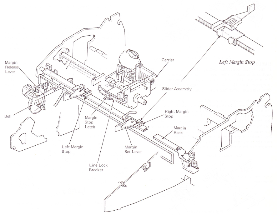
Figure 1 — Margin Control
BELLRINGER
As the carrier moves to the right-hand margin, the bellringer bellcrank slides over two vertical tabs on the linelock bracket. This causes the bellringer bellcrank to pivot around its mounting stud and cam the bellringer bail to the front of the machine. An extension of the bellringer bail forces the keyboard lockout interposer into the selector compensator tube.
As the bellringer bail is pushed to the front of the machine, the bell clapper bellcrank pivots the bell clapper away from the bell (Figure 2). Further rotation of the bail causes the bell clapper bellcrank to slip off the bell clapper allowing the bell clapper to restore to rest. The pull of the bell clapper spring and the force of the bell clapper returning to rest causes it to overthrow its rest position and strike the bell. When the bellringer bail is allowed to restore, the bell clapper bellcrank resets above the bell clapper ready for the next operation.
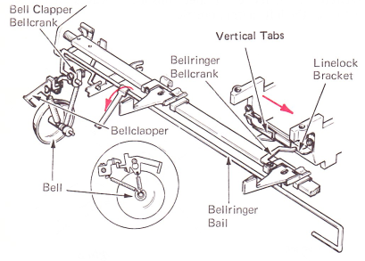
Figure 2 — Bellringer
LINELOCK
If the typist continues typing after the bell rings, the keyboard is locked after several spaces to prevent typing in the margin. The keyboard is locked by forcing a special interposer into the selector compensator tube to prevent depressing any other interposer (Figure 3).
As the carrier moves to the right-hand margin, the bellringer bellcrank moves into the path of two vertical extensions on the linelock bracket. This causes the bellringer bellcrank to pivot about its mounting stud and cam the bellringer bail to the front of the machine. An extension of the bellringer bail forces the keyboard lockout interposer down and into the selector compensator tube. This action in turn prevents any further depression of the selector keylever interposers into the compensator tube until the linelock mechanism has restored to its normal rest position.
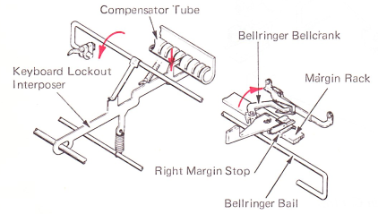
Figure 3 — Linelock Mechanism
LINELOCK MECHANISM (LEVEL 1)
The Level 1 linelock mechanism locked the keyboard in the same way as the present mechanism. However,the keyboard lock interposer used several parts. The bellringer bail operated the keyboard lock interposer which through an extension spring pulled the keyboard lock bellcrank into the compensator tube (Figure 4).
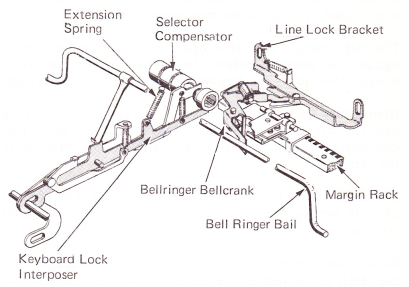
Figure 4 — Linelock Mechanism — (Level 1)
MARGIN RELEASE
The margin release mechanism allows an operator to type past the left and right margins without changing the position of the margin stops. The margin release operates by rotating the margin rack so the margin stops move upward out of the path of the margin stop latch on the linelock bracket (Figure 5).
The margin release keylever pivots at the left side of the keyboard. Depression of the margin release keylever causes the rear of the margin rack to rise. A lug on the left end of the margin rack remains in the path of the margin stop latch to unlatch the carrier return if it is operated with the margin release keylever depressed. An extension spring restores the mechanism and holds it in the rest position.
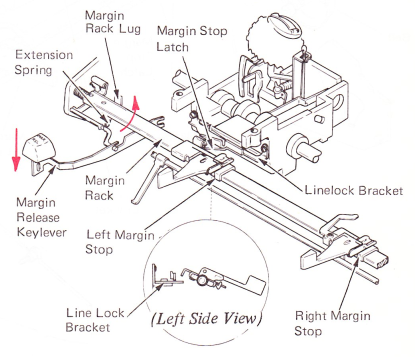
Figure 5 — Margin Release