Selectric Resources
"CORRECTING" MECHANISM ADJUSTMENTS
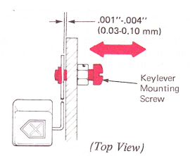
1. Correcting Keylever Side Play — Adjust the keylever mounting screw so the correcting keylever has .001”-.004” (0.03-0.10 mm) side play,
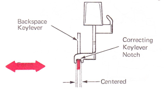
2. Backspace Keylever — Form the backspace keylever so that it centers in the notch on the correcting keylever.
NOTE: Adjustments 3 through 5 are for machines with a field-installed correcting keybutton interlock.
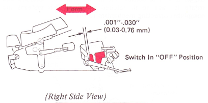
3. Correcting Keybutton Interlock (Front To Rear) — Form the correcting keybutton interlock front to rear to get .001”-.030” (0.03-0.76 mm) between the horizontal part of the correcting keylever and the interlock.
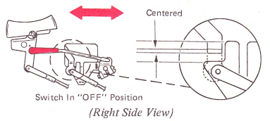
4. Lockout Bail Link — With the switch in the OFF position, adjust the lockout bail link so the horizontal part of the correcting keylever is centered on the locking surface of the correcting keybutton interlock.
5. Correcting Keybutton Interlock And Lockout Bail (This part is not on all machines). — With the machine in the OFF position, adjust the correcting keybutton interlock for the following conditions:
a. Position the correcting keybutton interlock left to right to get .005”-.020” (0.13-0.51 mm) between the keyboard side frame and the lockout arm.
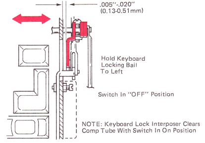
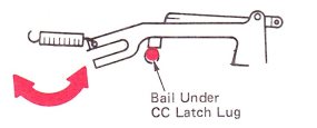
b. Position the lockout bail under the cycle clutch latch lug.
NOTE: The keyboard lock interposer must clear the compensator tube with machine in the ON position.
6. Correcting Keylever Link — Adjust the correcting keylever link clevis so that the mode latch releases the mode actuating bellcrank, at the same time or slightly before, the backspace cam is released.

7. Mode Actuating Bellcrank — Form the lug on the mode actuating bellcrank so the bellcrank overthrows the mode latch by .005”-.010” (0.13-0.25 mm) when the escapement trigger lever is fully operated.
Check this adjustment on the cam that supplies the least amount of overthrow, either the spacebar or the escapement cam.
NOTE: Check trigger knockoff in the escapement adjustments after making this adjustment.
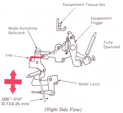
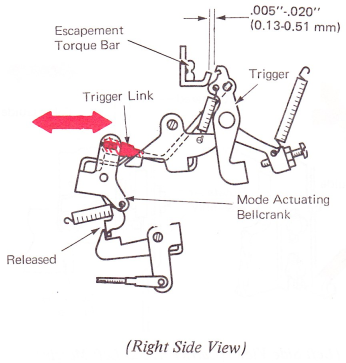
8. Trigger Link — With the mode actuating bellcrank released, adjust the trigger link clevis so that the working surface of the trigger clears the escapement torque bar lug by .005”-.020” (0.13-0.15 mm).
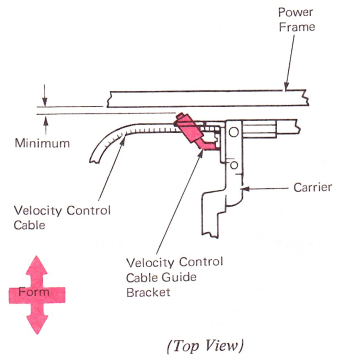
9. Cable Guide Bracket — Form the velocity control cable guide bracket as far to the rear as possible with minimum clearance to the power frame. The bracket must keep the velocity control cable from getting behind the carrier.
NOTE: Check that the guide bracket clears the frame at the far left margin.
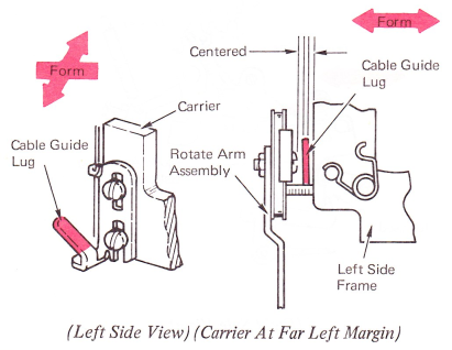
10. Cable Guide Lug — Form the cable guide lug on the tape lift assembly front to rear so it is centered between the rotate arm assembly and the power frame when the carrier is at the far left margin.
NOTE: Be sure to maintain enough left-to-right angle to ensure the velocity control cable moves under the carrier when the carrier is at the far left margin.
NOTE: The platen adjustments must be correct before making the following adjustments.
11. Cardholder — With the copy control lever forward, adjust the cardholder mounting brackets to satisfy the following condition:
a. Front to rear so that the cardholder clears the platen by .020”-.030” (0.51-0.76 mm). Adjust the right bracket and form the left leg to meet this condition.
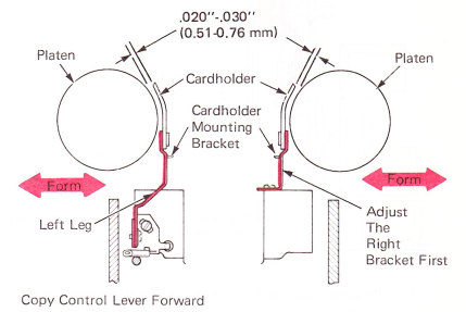
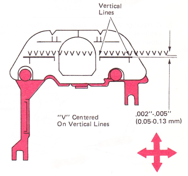
b. Position the mounting bracket left and right and up or down so the horizontal line on the cardholder rests .002”-.005” (0.05-0.13 mm) below the writing line. The vertical lines must be centered on a printed character.
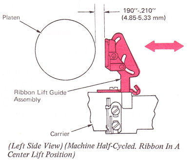
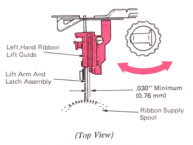
12. Ribbon Lift Guide (Left Only) —
a. With the machine half cycled and the ribbon in the center lift position, adjust the left ribbon lift guide assembly front to rear for .190”-.210” (4.83-5.33 mm) between the rear face of the guide and the platen.
NOTE: This clearance can be easily checked by using the handle end of the 224 backspace adjustment wrench (P/N 9900369).
b. Position the left-hand lift guide left to right for .030” (0.76 mm) minimum clearance between the front of the lift guide and the left arm and latch assembly.
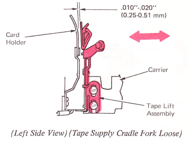
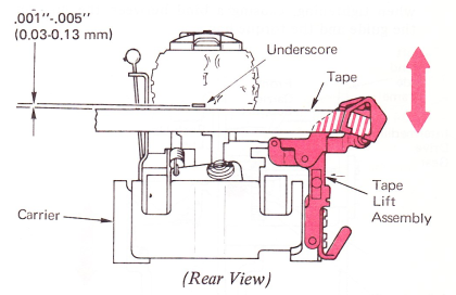
13. Tape Lift Assembly — Adjust the tape lift assembly to satisfy the following conditions:
a. Front to rear so that the tape clears the front of the cardholder by .010”-.020” (0.25-0.51 mm). The tape supply cradle fork must be loose while making this adjustment (reference adjustment 14).
b. Vertically so that the bottom of the underscore clears the top of the tape by .001”-.005” (0.03-0.13 mm) when the tape is at rest and the underscore is in the print position.
14. Tape Supply Cradle Fork — Position the cradle fork so that it centers in the groove of the stud mounted on the tape lift assembly.

15. Torque Bar Back-Up Lug —
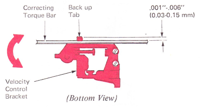
a. PRE-FTB — Adjust the velocity control bracket so that the back-up lug on the bracket has a clearance of .001”-.006” (0.03-0.15 mm) with the correcting torque bar with the carrier positioned at the far left margin.
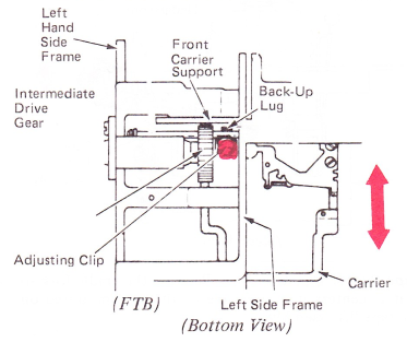
b. FTB — Move the carrier to the left until the adjusting clip is positioned between the intermediate drive gear and the LH side frame. Adjust the clip front to rear for .065”-.070” (1.65- 1.78 mm) clearance between the back-up lug and the front support.
Check to ensure the clip has not rotated clockwise when tightening. causing a bind between the lugs on the guide and the torque bar.
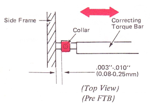
16. Correcting Torque Bar End Play — Position the collar on the left end of the correcting torque bar left or right so the torque bar has .003”-.010” (0.08-0.25 mm) end play.
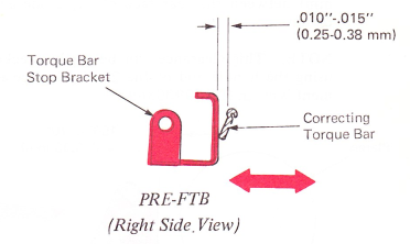
17. Torque Bar Stop Bracket (PRE-FTB Only) — Adjust the torque bar stop bracket located at the right end of the torque bar front to rear for a clearance of .010”-.015” (0.25-0.38 mm) between the bracket and the top of the correcting torque bar.
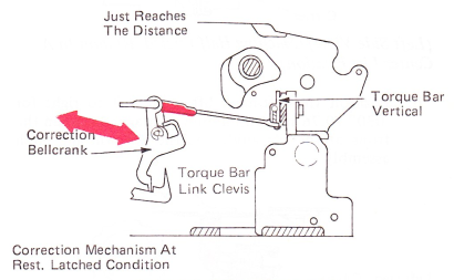
18. Torque Bar Link (Preliminary) — Manually hold the torque bar vertical and adjust the torque bar link clevis to just reach the distance to the correction bellcrank. The pin in the clevis must be in the front position of the slot in the bellcrank; reconnect link. THE TORQUE BAR SHOULD NOW BE VERTICAL.
19. Lift Actuating Arm (PRE-FTB) — With the torque bar at rest, form the lift actuating arm for a clearance of .001”-.005” (0.03-0.13 mm) between the lift actuating arm and the correcting torque bar at the closest point.
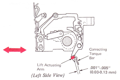
NOTE: This adjustment can most easily be made from the bottom of the machine.
Lift Arm Stop —
a. Lift Arm Stop (FTB) — Adjust the lift arm stop for .001”-.005” (0.03-0.13 mm) clearance between the working surface of the lift actuating arm and the torque bar.
Form the tip of the lift actuating arm to get a minimum of .002” (0.05 mm) below the bottom of the torque bar, at the torque bar’s lowest point (center of writing line).
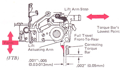
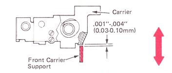
b. Raise the front carrier support for .001”-.004” (0.03-0.10 mm) clearance with no carrier binds. If adjustment of support does not get clearance below the torque bar, form the actuating arm down. Check to ensure the lift actuating arm is free of binds if forming was required. Check for possible interference with gear train idler gear.
20. Lift Arm Latch (PRE-FTB) — Adjust the lift arm latch to satisfy the following conditions:
a. With the correcting mechanism at rest, position the lift arm latch front to rear so the tape lift cam follower clears it by .010”-.015” (0.25-0.38 mm).

b. With the print mechanism at rest and the correcting torque bar operated, the bottom of the lift arm latch must clear the lift cam follower by .005”-.010” (0.13-0.25 mm).

Lift Arm Latch (FTB) —
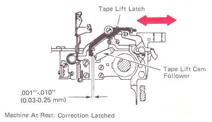
c. Tape Lift Latch Front To Rear — With the machine at rest, adjust the lift latch front to rear for .001"-.010” (0.03-0.25 mm) clearance between the rear of the tape lift cam follower and the front lug on the tape lift latch.
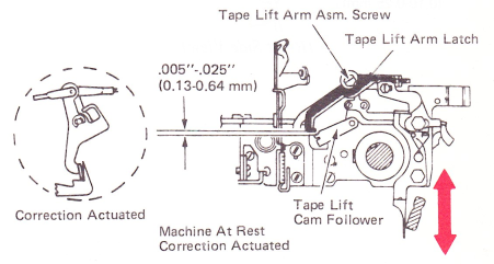
d. Tape Lift Latch Height — With the machine at rest and the correction mechanism activated, adjust the tape lift arm latch vertically for a .005”-.025” (0.13-0.64 mm) clearance between the bottom of the latch and the lift cam follower.
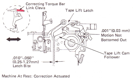
Torque Bar Link Adjustment (Final) — With the machine at rest and the correction mechanism actuated, adjust the link for a minimum overlap of .010”-.050” (0.25-1.27 mm) overlap. Also, the actuating arm must not be bottomed against the arms’ mounting stud. If there is no forward travel of the arm assembly, readjust the link for a minimum of .001” (0.03 mm) motion. This is to make sure the system is not binding off.
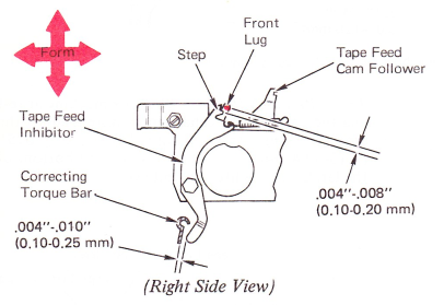
21. Tape Feed Cam Follower, Front Lug (PRE-FTB) — With the machine at rest, form the front lug on the follower to satisfy both of the following conditions:
a. Front to rear so the tape feed inhibitor clears the correcting torque bar by .004”-.010” (0.10-0.25 mm) at the closest point across the writing line with all parts at rest.
b. Vertically so that the bottom of the lug clears the tape feed inhibitor step by .004”-.008” (0.10-0.20 mm).
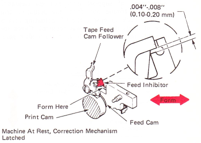
c. Tape Feed Inhibitor (FTB) — With the machine at test, form the tape feed inhibitor lug front to rear for a .001”-.015” (0.03-0.38 mm) clearance between the vertical surface of the inhibitor and the front surface on the tape feed cam.

d. With the tape feed cam follower on the high point of the cam (machine at rest) and the correction mechanism latched, form the feed inhibitor left to right for a clearance of .004”-.008” (0.10-0.20 mm) between the latching surface of the inhibitor and the bottom lug on the tape feed cam follower.
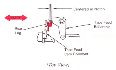
22. Tape Feed Cam Follower, Rear Lug — Form the rear lug on the tape feed cam follower left or right so it centers in the notch in the tape feed bellcrank.
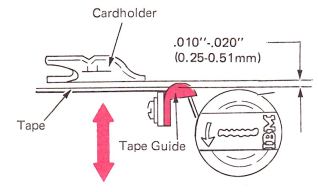
23. Tape Guide — The tape guide mounting bracket must be positioned to meet the following conditions:
a. Position the tape guide up or down so the used tape is centered on the take-up spool.
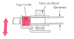
b. Position the tape guide front to rear so the tape clears the cardholder by .010”-.020” (0.25-0.51 mm).
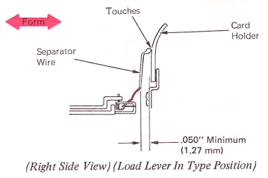
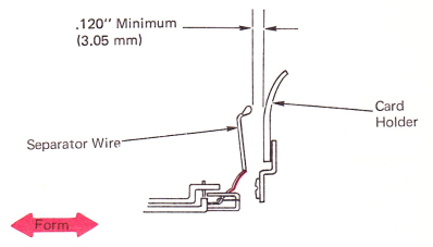
24. Separator Wire — Form the separator wire to satisfy the following conditions:
CAUTION: Do not type with the tape load lever in the load position. The typehead may engage the separator wire and result in rotate tape breakage.
a. Left to right so that the wire clears the typehead by .060”-.070” (1.52-1.78 mm) when the typehead is in the print position and the load lever is in the type position.

b. With load lever in the type position, the top of the separator wire should just touch the cardholder while maintaining a minimum of .050” (1.27 mm) clearance at the bottom of the vertical part of the separator wire.
c. With the load lever in the load position, the top of the separator wire must clear the cardholder by at least .120” (3.05 mm).
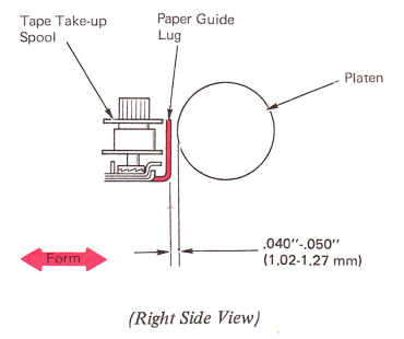
25. Paper Guide Lug — Form the paper guide lug front to rear so that it clears the platen by .040”-.050” (1.02-1.27 mm).
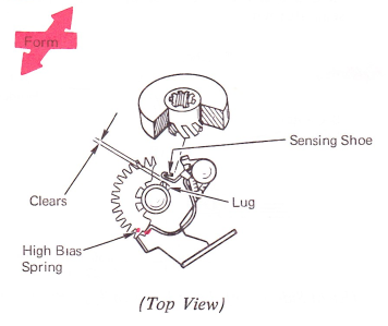
26. High Bias Spring — Form the vertical tip of the high bias spring in or out so that the sensing shoe clears the lugs on the tape supply spool when the mechanism is at rest.