Selectric Resources
MANUAL VELOCITY CONTROL OPERATIONAL THEORY
The manual velocity control provides the operator with a means of controlling the automatic velocity control feature. A control wheel mounted just to the right of the ON/OFF keybutton determines keyboard velocity. When the control wheel is in the center or normal position, the keyboard is in the automatic velocity control mode. With the control wheel rotated away from the operator, all keyboard positions will be low velocity. The control wheel must be held in this position. When the control wheel is rotated toward the operator, the keyboard will be in high velocity. This position is maintained by a detent and need not be held (Figure 1).
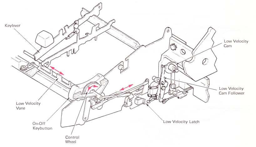
Figure 1 — Manual Velocity Control
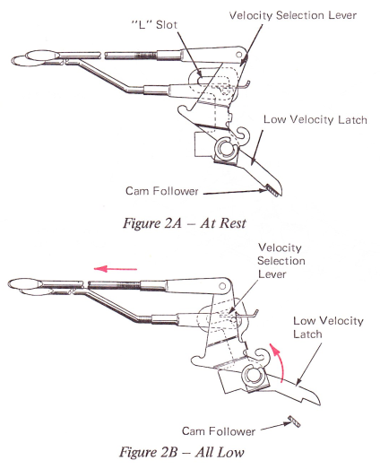
The velocity selection lever is mounted to the right of, and on the same stud as, the low velocity latch. A link extends between the top of the velocity selection lever and a lower extension on the control wheel (Figure 2A). When the control wheel is rotated away from the operator, the link pulls the top of the velocity selection lever toward the front of the machine. A lug on the velocity selection lever contacts the low velocity latch and rotates it away from the low velocity cam follower stop. With the control wheel held in this position, the cam follower is allowed to provide low velocity from any keyboard position (Figure 2B).
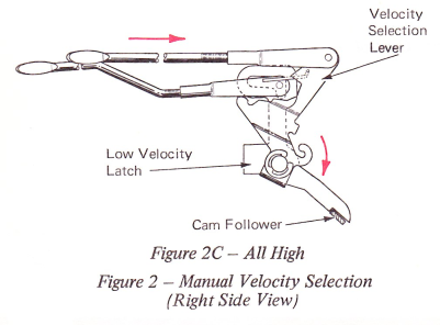
When the control wheel is rotated toward the front of the machine, the top of the velocity selection lever is pushed toward the rear of the machine. Another lug on the velocity selection lever contacts the low velocity link and pushes it up out of the foot of the “L” slot. When an interposer operates the low velocity vane, the low velocity bellcrank will pull the link and the link will slide down the slot and will not be able to move the latch (Figure 2C).