Selectric Resources
KEYBOARD ADJUSTMENTS
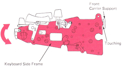
1. Keyboard Position — With the extensions on the keyboard side frame touching the front carrier support, rotate the keyboard until the filter shaft bearings are held tightly between the side plates and the power frame. Tighten mounting screws.
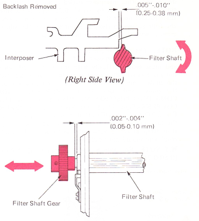
2. Filter Shaft — Loosen the filter shaft gear and rotate the filter shaft so that the working surface of the filter shaft clears the rear of any latched interposer by .005”-.010” (0.25-0.38 mm). This adjustment should be made with the machine at rest and all gear train backlash removed in the forward direction. Be sure to maintain .002”-.004” (0.05-0.10 mm) end play of the filter shaft.
This adjustment affects the timing of all the cams mounted on the filter shaft.
Not enough clearance between the filter shaft and the interposers could allow the filter shaft to stop just under the rear of the interposers. The keyboard would not operate, because the interposers could not be depressed.
Excessive clearance would delay the operation of the interposers. The selector latches would not be pulled forward from under the latch bail before the bail started moving downward. This would result in excessive wear and a noisy operation as the latches were pulled from under the bail. This condition is referred to as “popping latches.”
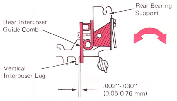
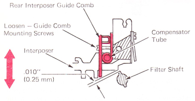
3. Rear Bearing Support — Adjust the rear bearing support to get .002”-.030” (0.05-0.76 mm) between the rear interposer guide comb and the vertical lugs on the interposers. Check this across the entire keyboard
Touch problems can occur if the rear lug of the interposer is contacting the rear interposer guide comb. There should be a minimum of .002” (0.05 mm) clearance. If not, the two keylever fulcrum support mounting studs may be loosened and the guide hit lightly to the rear. If excessive clearance (more than the pusher end of the spring hook) is present, bridging (malselection) can occur. The reason is that the interposer does not extend into the compensator balls far enough.
W.T.NOTE: This applies to machines with aluminum support only
4. Rear Interposer Guide Comb — Adjust the guide comb vertically so that with the “N” interposer latched down, any other interposer pulled down will clear the tip of the filter shaft by .010" (0.25 mm) as the filter shaft rotates under it. To make this adjustment, loosen the four screws on the guide comb. Check the adjustment at several points across the filter shaft.
NOTE: The selector compensator tube is mounted to the rear of the interposer guide comb by two screws and must move vertically with the guide comb when the guide comb adjustment is made. Be sure to loosen the guide comb mounting screws before trying to move the guide comb. DO NOT HAMMER THE GUIDE COMB INTO POSITION AS THIS CAN CAUSE THE COMPENSATOR TUBE TO SHIFT WITH REFERENCE TO THE GUIDE COMB. The vertical position of the tube on the guide comb is set with reference to the stop strap attached across the bottom of the guide comb and should not be changed.
W.T.NOTE: For Punch Press Support; .020”-.030” (0.50-0.75 mm).
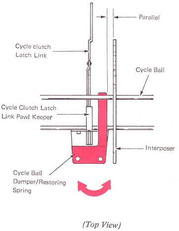
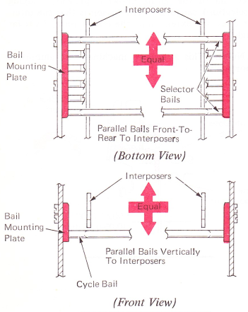
5. Bail Mounting Plate — Position the left-hand bail mounting plate to satisfy the following conditions. The selector bails should be parallel front-to-rear with the lugs on the interposers. At the same time, the cycle bail must be parallel vertically with the lugs on the interposers.
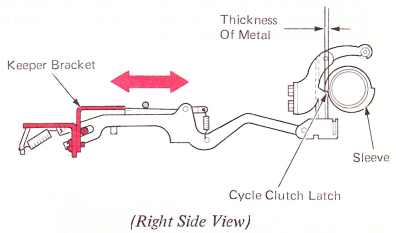
6. Keeper Bracket — Adjust the keeper bracket front to rear so that the cycle clutch latch engages the sleeve by the thickness of the keeper bracket with the machine at rest.
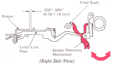
7. Cycle Clutch Latch Restoring —
Level 1 — Adjust the scissor restoring mechanism so that the latch link pawl overthrows the keeper by .030”-.045” (0.76-1.14 mm).
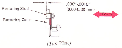
Level 2 — Adjust the restoring stud vertically so the latch link pawl overthrows the keeper by .015”-.025” (0.38-0.64 mm) before it restores. Hand cycle the machine and check this clearance on both sides of the restoring cam. Adjust the stud on the side providing the least amount of motion.

Form the restoring arm left to right so the restoring stud is flush to .015” (0.38 mm) inboard from the left edge of the restoring cam.
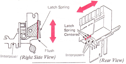
8. Interposer Latch Springs — Adjust the left and right group of interposer latch springs so the end of the latch springs are flush with the bottom of the interposer.
NOTE: Latch springs should be centered over the interposers.
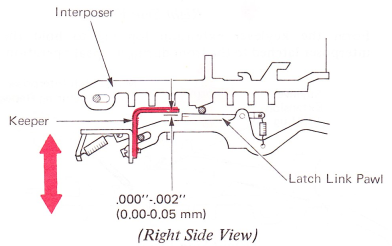
9. Cycle Clutch Keeper — Adjust the keeper vertically to get .000"-.002” (0.00-0.05 mm) clearance between the cycle clutch latch link pawl and the lower side of the keeper. Latch down an interposer, and hand cycle the character until that interposer is released from the compensator tube. Then, latch the same interposer a second time (placing that character into storage), and continue hand-cycling until the cycle clutch latch is point to point with the keeper during the restoring part of the first character’s cycle. The cycle clutch latch keeper may now be moved up or down to get .000”-.002” (0.00-0.05 mm) and the cycle clutch latch will not move in the latched mode. Then, check the clearance with various interposers latched down.
The interposer latch spring adjustment may need to be readjusted to maintain .000”-.002” (0.00-0.05 mm) clearance across the keyboard.
NOTE: This clearance should be maintained on the low side of the adjustments. Too much clearance can cause a wrong selection because of flicking action on the keylevers, causing the cycle clutch to be released without latching an interposer down. As a result, the filter shaft will not drive an interposer forward and a wrong character will be printed.
Not enough clearance does not ensure that the clutch will be released when an interposer is latched down. If an interposer is latched down without releasing the cycle clutch, the keyboard will be locked because the interposer will remain in the compensator tube.
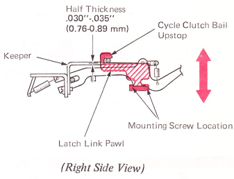
10. Cycle Bail Upstop — Adjust the cycle clutch bail upstop vertically so the cycle clutch latch link pawl engages the cycle clutch keeper by half the thickness with the machine at rest. This can be checked by making the center of the marked line on the latch link pawl even with the bottom of the keeper. The bail stop is mounted with two nuts and two screws. These nuts
and screws also control the position of the character interrupter bail plate. In order to adjust the cycle clutch bail stop, loosen both nuts and only the front screw. Do not loosen the rear screw.
Not enough engagement will increase the possibility of a repeat cycle because positive latching is not ensured. Excessive engagement will affect the touch of the keyboard because the latch pawl must be moved further in order to operate the cycle clutch.
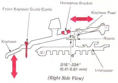
11. Front Keylever Guide Comb — Adjust the front keylever guide comb vertically for .016”-.024” (0.41-0.61 mm) clearance between the keylever pawl and the interposer lug as the keylever pawl resets above the interposer.
To check this adjustment, turn the power on and depress and slowly release keybuttons on the right, left, and center of the keyboard.
Keylevers that do not meet this adjusment may be formed at the horseshoe bracket.
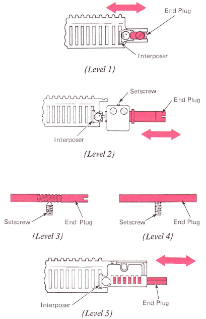
12. Compensator Tube — Adjust the compensator by using the following procedure: Tilt machine up, loosen the right end plug and latch out position forty-three interposer. Push the end plug tight against the balls and depress the H keylever until position forty-three interposer moves slightly to the right. Tighten the end plug. Repeat this procedure for the left side of the keyboard using position zero interposer and H keylever.
13. Repeat Keylever — Level 2 — Form the extension lug on the keylever so that the hyphen underscore will print one character at a time when operated with normal pressure and will repeat with increased pressure. When the keybutton is bottomed, it must not bind off the repeat operation.

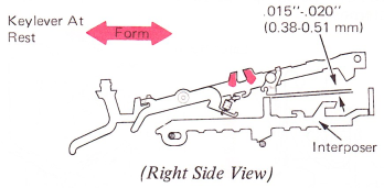
Row 4, Level 2 — With the keylever at rest, form the horseshoe bracket to get a clearance of .015”-.020” (0.38-051 mm) between the keylever pawl and the interposer.
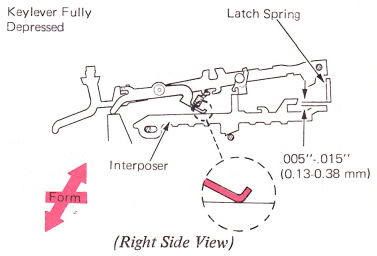
With the keylever fully depressed, form the extension to get .005”-.015” (0.13-0.38 mm) between the interposer and the interposer latch spring.
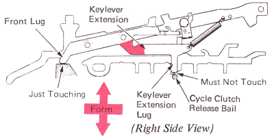
Row 4, Level 1 — Form the keylever extension to get a minimum clearance, without contact, between the keylever extension lug and the cycle clutch release bail. The front lug of the keylever extension should just contact the front guide comb support while viewing this adjustment.
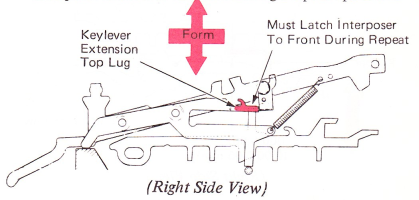
Form the keylever extension top lug to hold the interposer latched to the front during a repeat operation.
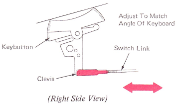
14. Switch Link — Adjust the switch link clevis so the on/off keybutton matches the slope of the keyboard in the off position.
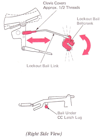
15. Lockout Bail Link And Bellcrank — With the switch in the off position, adjust the clevis to cover approximately one-half the threads on the link. Loosen the screw on the lockout bail bellcrank and position the lockout bail under the cycle clutch latch lug. Tighten the screw.
NOTE: A slow or hard keyboard may be caused by the one-piece keyboard locking interposer being partially engaged in the bail compensator tube. Check the adjustment of the keyboard locking bail and ensure that it positively locks the keyboard with the switch in the off position, yet unlocks the keyboard in the on position and allows the locking interposer to clear the
compensator balls.
NOTE: The blue tip of the locking interposer spring should be attached to the interposer.
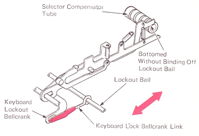
16. Keyboard Lock Bellcrank Link — Adjust the clevis so the bellcrank is fully bottomed in the selector compensator tube without binding off the motion of the lockout bail.
17. Cycle Bail Damper Spring (W.T.) — Adjust parallel to interposers. Make this adjustment with the keeper bracket adjustment.