Selectric Resources
FILM RIBBON ADJUSTMENTS
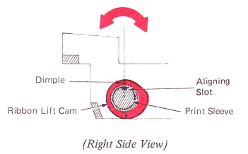
1. Ribbon Lift Cam — Adjust the ribbon lift cam so the aligning slot is aligned with the front edge of the print sleeve keyway.
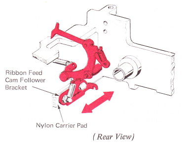
2. Ribbon Feed Cam Follower Bracket — With the nylon carrier pad against the carrier casting, the ribbon feed cam follower bracket should be centered left to right in its mounting hole. Keep the bottom of the bracket parallel to the carrier pad.
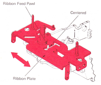
3. Ribbon Plate — Adjust the ribbon plate left to right so the ribbon feed pawl is centered in the operating slot. The ribbon feed pawl must move freely front to rear in its slot.
4. Ribbon Feed Cam Follower Stud (Level 2) — Hand cycle the machine and observe the lift control lever stud as it moves from the low point to the high point on the ribbon feed and lift wheel. Adjust the ribbon feed cam follower eccentric stud so the ribbon lift control lever stud overthrows the detent notch in the ribbon feed and lift wheel by .005”-.015” (0.13-0.38 mm).
Level 1 — Machines not equipped with the detent positions on the ribbon feed and lift wheel should be adjusted so the lift control lever roller is centered on the high surface of the ribbon feed and lift wheel.
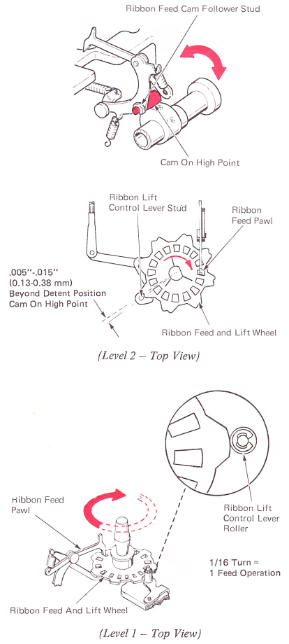
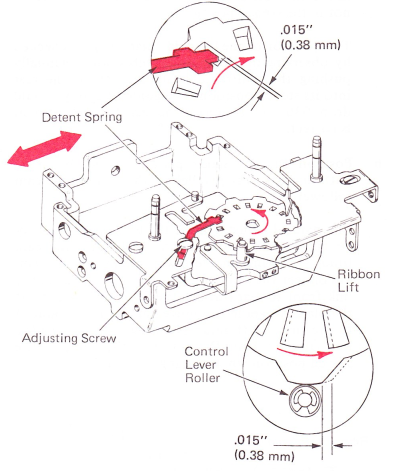
5. Ribbon Feed and Lift Wheel Detent Spring (Level 1 Only) — Adjust the detent spring so that the ribbon feed and lift wheel moves .015" (0.38 mm) after the detent spring drops into a feed window. To check the adjustment, hand cycle the machine and observe the detent spring as the ribbon lift control lever roller moves from the low point to the high point on the ribbon feed and lift wheel.
6. Brake Actuating Lever (Level 1 Machines Only) — Form the lug on the brake actuating lever so the supply spool brake is allowed to just bottom in the ratchet teeth of the supply spool when the machine is at rest.

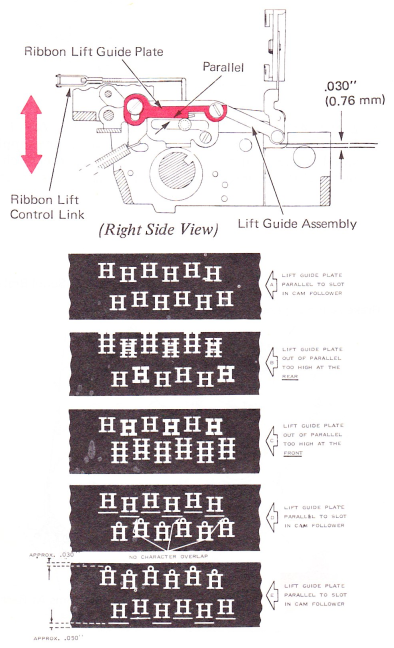
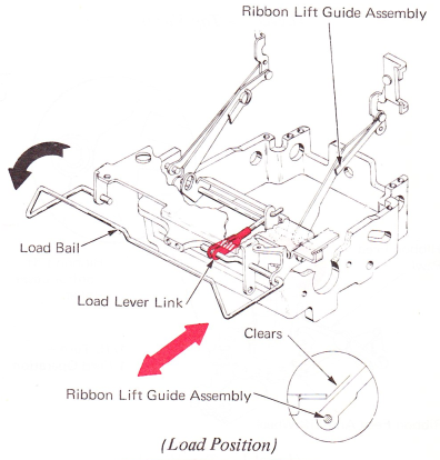
7. Ribbon Lift Guide Plate — With the ribbon lift cam follower on the low point of the ribbon lift cam, position the lift guide plate on the arm of the lift guide assembly to satisfy the following conditions:
a. Position the lift guide plate vertically so the rear of the lift guide assembly rests .030” (0.76 mm) above the carrier casting when the stencil lever is not in the stencil position.
This position of the lift guide plate may be checked by observing the lift guide assembly while manually pushing the control link all the way to the rear into its stencil position. The guide assembly should drop .030” (0.76 mm) at the rear if the adjustment is correct.
b. Position the lift guide plate horizontally so its bottom surface is parallel to the slot in the cam follower.
The parallel adjustment of the lift guide plate may be checked in the following way. With the cam follower resting on the low point of the lift cam, disconnect the control link and manually slide the link front to rear through the four lift positions. If the plate is parallel, no movement will be produced to the ribbon lift guide assembly while sliding the link front to rear. Do not slide the link into the stencil position while making this check.
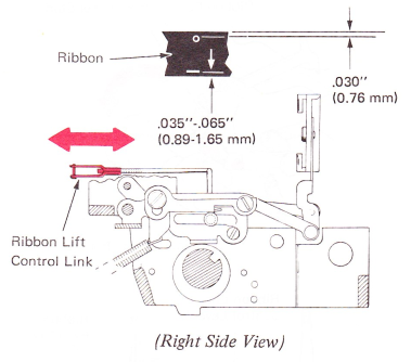
8. Lift Control Link — Adjust the clevis on the ribbon lift control link so the lowest underscore prints .035”-.065” (0.89-1.65 mm) from the bottom edge of the ribbon. The degree character should be at least .030” (0.76 mm) from the top of the ribbon.
NOTE: The adjustment of the ribbon lift control link positions the lift pattern on the ribbon and does not have any effect on the distance between each of the four lift positions in the pattern.
Adjustments 9 through 15 are for level 1 mechanisms only.
9. Load Lever Link (Level 1 Only) — Adjust the load lever link to raise the ribbon lift guide assembly as high as possible without binding off on either the ribbon feed plate or the take-up spool when the load bail is in the load position.
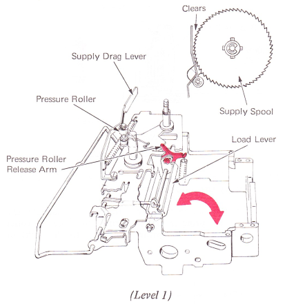
10. Pressure Roller Release Arm (Level 1) — Adjust the pressure roller release arm below its binding screw, located on the left end of the load lever, so the supply drag lever will be pushed forward by the pressure roller to just clear the front edge of the supply spool.
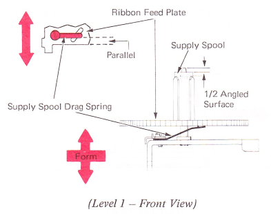
11. Supply Spool Drag Spring (Level 1) — Adjust the supply spool drag spring to satisfy the following conditions:
a. Position the drag spring parallel to the front edge of the ribbon feed plate.
b. With the “C” clip removed, the drag spring should raise the supply spool so half of the pointed surface on top of the pivot stud is extended above the top face of the spool. Form the drag spring up or down to get this condition.
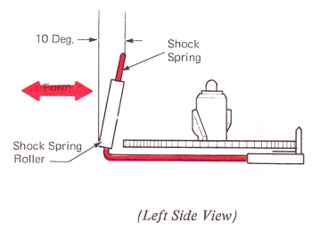
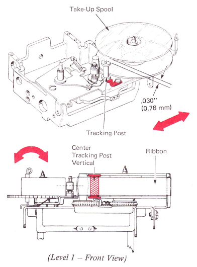
12. Shock Spring (Level 1) — Position the shock spring so it is approximately .040” (1.02 mm) to the right and parallel to the edge of the ribbon feed plate. The shock spring should be formed to make the roller on the shock spring 10 degrees to the left of vertical.

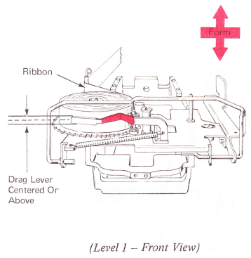
13. Drag Lever (Level 1) — Form the drag lever so that it contacts the outer part of the ribbon on the supply spool at the center, or slightly above. Do not form it front to rear.
NOTE: After forming the lever, make sure that it does not bind on its pivot screw. If the supply spool drag lever contacts the ribbon below center, the outer part of the ribbon spool will be moved up, which may cause the ribbon to come off of the spool.
14. Tracking Post (Level 1) — Position the tracking post under its mounting screw so it clears the flanges of the clear take-up spool by .030” (0.76 mm). Form the tracking post at the bottom so the tracking post is vertical to the feed plate. If the tracking post is vertical. the ribbon will be centered as it passes between the two flanges of the clear take-up spool. It should
also track on the center of the feed roller and evenly between the two flanges of the tracking post without touching either flange.
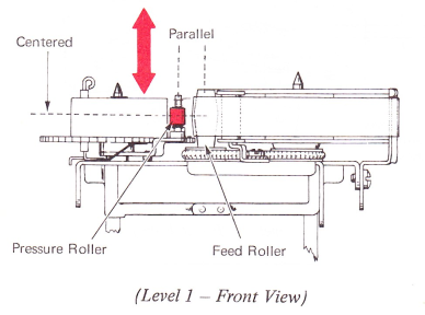
15. Pressure Roller (Level 1) — Adjust the pressure roller vertically on its mounting stud so it engages the center of the feed roller. The pressure roller mounting stud should be parallel to the previously aligned tracking post.
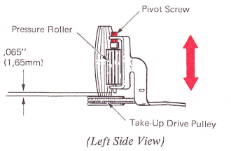
16. Pressure Roller (Level 2 Only) — Machines with the adjustable pressure roller should be adjusted so the lower end of the pivot screw clears the take-up drive pulley by .065” (1.65 mm).
17. Shock Spring (Level 2 Only) — Form the shock spring to satisfy the following conditions:
a. When viewed from the front of the machine, the shock spring should be formed to make the roller on the shock spring 5 degrees to the right of vertical.
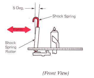
b. When viewed from the side, the shock spring should be formed so the roller is 10 degrees to the right of vertical.