Selectric Resources
FABRIC RIBBON OPERATIONAL THEORY
The fabric ribbon mechanism can be separated into two mechanisms. They are the ribbon lift mechanism and the ribbon feed mechanism. The ribbon lift raises the ribbon to the printing position before the typehead prints and then restores the ribbon to allow a visible writing line. The ribbon feed moves the ribbon laterally past the printing point to another part of the ribbon for the next typing operation. Included in the ribbon feed mechanism is the ribbon reversing mechanism, which changes the feeding direction when either end of the ribbon is reached.
The ribbon is a 9/16” (14.3 mm) ribbon in a throw away cartridge unit for clean handling. The cartridge unit contains two spools on which the ribbon is wound. The ribbon feeds from one spool to the other and back again. After the ink supply has been used up, the cartridge is thrown away, and a new cartridge installed (Figure 1).
Located to the right of the pointer on the carrier assembly is the ribbon load lever. When this lever is pushed to the right, it forces the ribbon lift guide into a high lift position to aid in changing the ribbon. A detent holds the load lever to keep the ribbon lift in the high lift position. The cartridge is then removed from the ribbon feed plate and the ribbon can be easily removed from the guide without touching the ribbon.
A new ribbon can be installed by reversing the above procedure. Angled lugs on the sides of the ribbon feed ratchets automatically guide the ribbon spools into the correct position. Guide lugs at each side of the feed plate maintain the lateral position of the cartridge. Retainer springs attached to the guide lugs hold the cartridge down to prevent vibration. After the ribbon is installed, the load lever is moved back to the left to allow the ribbon to restore to its normal position for a typing operation.
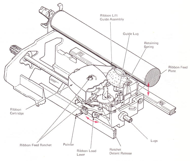
Figure 1 — Carrier Assembly (Fabric Ribbon Installed)
RIBBON LIFT
The ribbon lift mechanism consists of a lift cam, a ribbon lift cam follower, a control mechanism and the ribbon lift guide assembly (Figure 2). The lift mechanism is mounted to the carrier and moves with it. The ribbon lift cam is a single side cam that is attached by setscrews to the left side of the print sleeve. Each time a print cycle occurs, the cam makes one complete revolution.
The ribbon lift cam follower pivots on the carrier assembly above and to the rear of the cam. Each revolution of the cam raises the cam follower. The end of the ribbon lift control link fits into an elongated slot in the cam follower. The ribbon lift guide rests on the control link and pivots at the front of the carrier casting. As the cam follower is raised, the control link forces the ribbon lift guide assembly to pivot at the front and raise the rear of the assembly. A flat link from each side of the ribbon lift guide attaches to two pins at the front of the carrier to maintain the ribbon lift guide in a vertical position.
The ribbon lift guide assembly is spring loaded into the rest position to ensure that it will restore quickly and to prevent overthrow of the ribbon due to the speed of the lift mechanism (Figure 2).
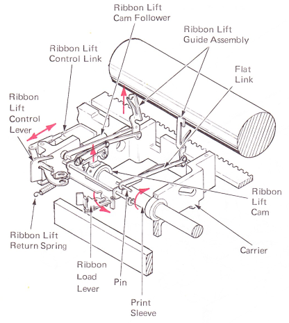
Figure 2 — Ribbon Lift Guide
The fabric ribbon mechanism has four lift positions. A lift position is selected by manually positioning the ribbon lift lever for stencil, low, medium or high lift position. The height to which the ribbon will be raised is determined by the position of the ribbon lift control link in the elongated slot of the cam follower. When the control link is to the rear of the slot, no motion is transferred to the lift guide assembly. When the control link is to the front of the slot, maximum motion is transferred to the lift guide assembly (Figure 3).
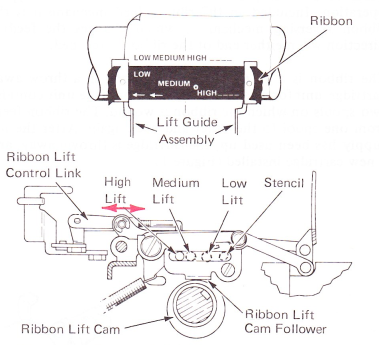
Figure 3 — Ribbon Lift Positions And Print Pattern (Right Side View)
RIBBON FEED OPERATION
The ribbon feed and reverse mechanism is mounted at the top of the carrier just in front of the typehead. The mechanism is removable as a unit for repair or replacement purposes.
The ribbon feed plate is made up of: two ribbon feed ratchets, a ribbon feed lever, a ratchet detent lever, a ribbon feed and reverse plate. and a bracket that is used to attach the ribbon feed lever. The feed and reverse plate has the ribbon feed pawl mounted to it with a shouldered stud so that it can pivot freely. The ribbon feed lever extends through an elongated slot in the feed and reverse plate so it can transfer the motion of the feed cam to front-to-rear motion of the feed pawl. The front-to-rear motion of the feed pawl is used to move a ribbon feed ratchet two teeth to the rear on each feed stroke. The ratchet to be fed is determined by the position of the ratchet detent lever (Figure 4).
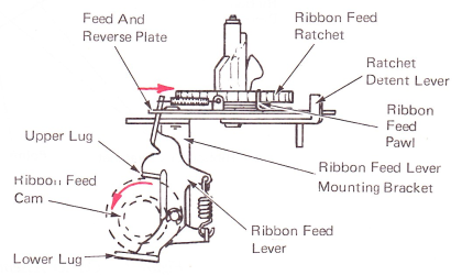
Figure 4 — Ribbon Feed Cam (Left Side View)
The ribbon feed ratchet assemblies rotate freely around their feed ratchet spindles. The ribbon supply hub on the feed ratchet extends through the ribbon cartridge and locks it to the hub so that the supply spool will turn with the ratchet. Two flat retainer springs are mounted on the ribbon feed plate at the rear so that they rest against the ribbon feed ratchets. The slight drag applied by the springs prevents unwanted turning of the supply spool (Figure 5).
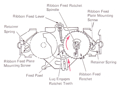
Figure 5 — Ribbon Feed Operation (Top View)
RIBBON REVERSE OPERATION
Each feed ratchet contains a small bellcrank called the ribbon reverse trigger (Figure 6). This trigger is spring loaded down by a small flat reverse trigger spring. The reverse trigger is held within the ribbon feed ratchet in the inactive position as long as ribbon is around the spool. During the last revolution of the supply spool, the reverse trigger is released into the active position. This causes the lower extension of the reverse trigger to drop into the path of a notch in the feed and reverse plate.
On the forward or restoring stroke of the plate, the reverse trigger contacts one side of the plate and prevents it from sliding forward. The other side continues to slide forward, causing a pivoting action on the plate about the point of contact. This makes the front of the plate pivot toward the opposite side, positioning the feed pawl in line with the ratchet teeth of the ribbon feed ratchet containing the empty ribbon spool. On the next feed stroke, the feed pawl will engage the ratchet teeth of the empty spool, causing it to feed ribbon (Figure 6).
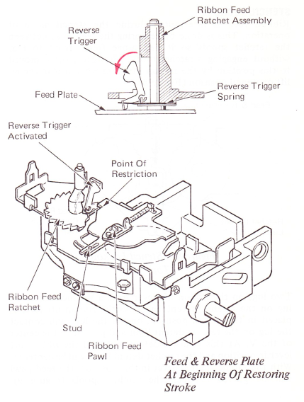
Figure 6 — Ribbon Reverse
Since the reversing action makes the full take-up spool become the supply spool and the empty supply spool become the take-up spool, it is necessary to disengage the ratchet detent lever from one feed ratchet and engage it with the other. This is done as part of the reversing operation. As the front of the feed and reverse plate moves, it causes the feed pawl to engage with the opposite feed ratchet, and pivots the ratchet detent lever to the opposite spool. A stud attached to the lever extends up through a slot in the feed and reversing plate connecting the two together. A hairpin spring, attached to this stud and to the feed plate, provides a toggling action to both the feed and reverse plate and the ratchet detent lever. In addition, the hairpin spring keeps the ratchet detent lever constantly spring loaded against the teeth of the feeding ratchet (Figure 7).
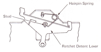
Figure 7 — Ratchet Detent (Bottom View)
STENCIL LOCKOUT
Ribbon feed is interrupted during the stencil mode of operation. This is done by centering the feed pawl between the ratchet spools so it can move freely front to rear without engaging a ratchet tooth. The feed pawl is moved to this position by the ribbon lift lever when it is in the no lift or stencil position (Figure 8).
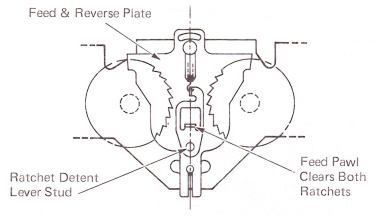
Figure 8 — Stencil Lockout (Top View)
Two lugs on the ribbon lift lever form a V which engages a lug on the ratchet detent lever. As the ribbon lift lever is placed in the stencil position, one of the lugs will contact the lug on the ratchet detent lever and push it to the center of the V. At this point, a detent will hold the ribbon lift lever in position and the ratchet detent lever will be centered. With the ratchet detent lever in this position, the feed pawl will be guided between the ratchet spools (Figure 9).
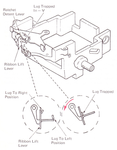
Figure 9 — Ratchet Detent Centered
Ribbon lift is also interrupted during the stencil mode of operation. When the ribbon lift lever is in the stencil position, the ribbon lift control link is allowed to move to the rear of the elongated slot in the lift cam follower (Figure 10). This places the end of the lift control link directly above the lift cam follower pivot point. As the lift cam rotates, the end of the lift control link simply rotates around the cam follower pivot point and no motion is transferred to the lift guide assembly. This prevents the ribbon from lifting into the path of the typehead during a stencil operation.
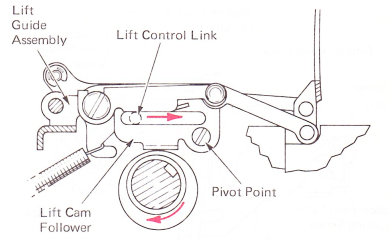
Figure 10 — Ribbon Lift Guide (Stencil Position) (Right Side View)
LEVEL 1 FEED
The old level ribbon mechanism contains a few more parts than the current mechanism, however, the operation is similar. The position of the feed pawl determines which ratchet is fed as the pawl moves to the rear. The feed pawl pivots on a pin below the ribbon feed plate and extends up through a hole in the plate. The pawl mounting allows left-to-right as well as front-to-rear movement. A restoring spring, attached to the pawl, restores the pawl to the rest position each time it operates. The spring also holds the pawl left or right into engagement with the correct ribbon feed ratchet depending upon the direction of the pull of the spring. The forward end of the spring is attached to a lever called the ribbon feed detent lever. The detent lever pivots on the ribbon feed plate. When the lever is moved to the right, the feed pawl is pivoted into engagement with the right feed ratchet. When the detent lever is moved to the left, the feed pawl engages to feed the left ratchet (Figure 11).
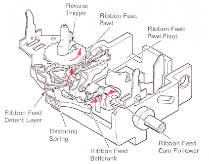
Figure 11 — Ribbon Feed Mechanism
The ribbon feed pawl is powered to the rear by the action of the ribbon feed cam. A sliding cam follower transfers the motion of the cam to the ribbon feed bellcrank which pivots and pushes the feed pawl to the rear. Enough motion is available from the cam to cause two teeth to feed on the ratchet.
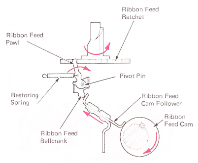
Figure 12 — Ribbon Feed Cam Motion (Right Side View)
As the feed pawl restores to the front, it slides across the teeth of the ratchet into the rest position (Figure 13). The drag of the pawl across the teeth can rotate the ratchet counterclockwise and unwind ribbon. To prevent any backward rotation, a detent pawl is spring loaded into the teeth of the ratchet to allow feed in one direction only.
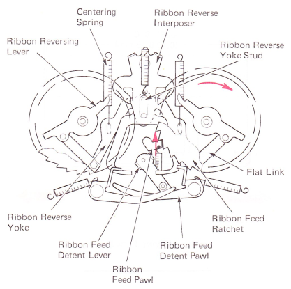
Figure 13 — Ribbon Feed Pawl (Rest Position — Top View)
LEVEL 1 REVERSE
To reverse the ribbon, a part of the reverse trigger pivots down through a hole in the ratchet into position below the ratchet as it does in the current mechanism (Figure 14). The empty spool rotates slightly further, causing the reverse trigger to contact and move the reverse lever, which pivots just below the ratchet. The reverse lever is connected by means of a flat link, to an arm of the reverse yoke below the ribbon feed plate. The yoke is pivoted by operation of the reverse lever. A stud on the yoke at the rear of the pivot points extends up through the feed plate into a slot in the reverse interposer. Movement of the yoke positions the front of the reverse interposer left or right, according to which ribbon spool is being emptied.
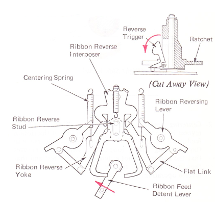
Figure 14 — Ribbon Reverse Mechanism(Top View)
Two things occur when the reverse interposer is positioned. A hook at the front of the interposer hooks around a lug on the ribbon feed detent lever (Figure 15). The interposer lever, mounted on the interposer, is positioned into the path of the ribbon feed pawl. The next operation of the ribbon feed cam causes the feed pawl to drive the reverse interposer to the rear. The hook at the front of the interposer pulls the lug of the detent lever to the rear, causing the detent lever to pivot to the opposite position. As the feed pawl restores, its spring pivots it over into engagement with the opposite ratchet.
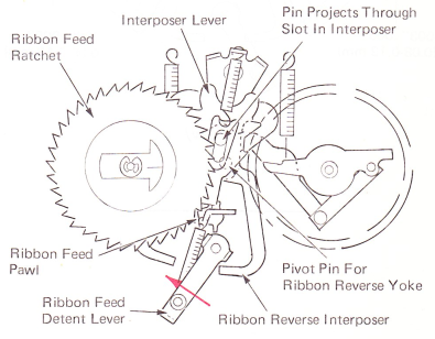
Figure 15 — Ribbon Reverse Mechanism (Active Position — Top View)