Selectric Resources
COVERS OPERATIONAL THEORY
There are three types of covers: tilt-up, console mount, and ring mount. First, we will describe the tilt-up covers, and then the differences between them and the other two types.
TILT UP COVERS
The cover assembly consists of three main sections. They are the top cover, center cover and bottom cover (Figure 1).
The center cover assembly has the paper guide attached to it. The paper guide may be removed by sliding the guide to the far right and pulling straight downward. A section of the cover material has been removed on the rear side to allow the guide to slide off easily.
The paper table is connected to the center cover assembly by two screws and two brackets. The paper table pivots on two studs mounted on the bracket to allow the platen to be removed from the machine.
A margin scale is attached to the lower extension of the top cover. The scale is marked to match the pitch of the typewriter. The margin scale is attached to the top cover by a glue that becomes active when IBM cleaning fluid is applied.
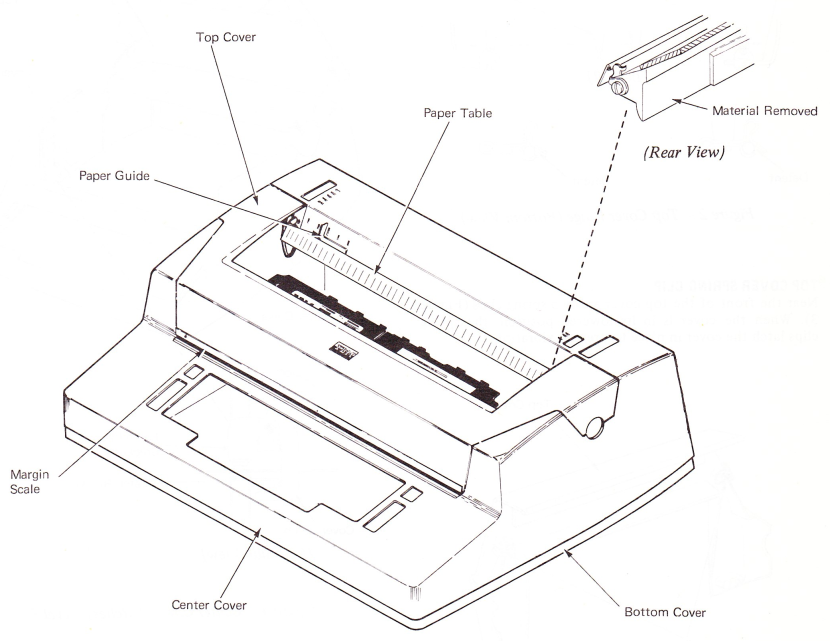
Figure 1 — Covers
TOP COVER HINGE
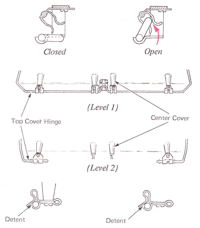
The top cover is attached to the center cover by a hinge at the rear. The hinge brackets are adjustable front-to-rear to allow for proper fit between the top cover and center cover. The hinge contains a detent that prevents the top cover from falling when it is in the raised position (Figure 2).
TOP COVER SPRING CLIP
Near the front of the top cover are two spring clips (Figure 3). When the cover is in its lowered position, the spring clips latch the cover in place to prevent vibration.
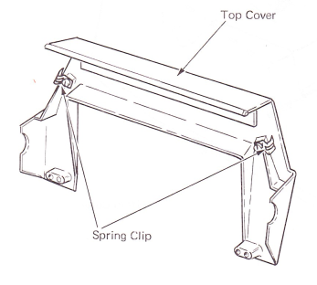
Figure 3 — Top Cover Spring Clip (Cover Raised)
CENTER AND BOTTOM COVERS
There are three basic levels of center and bottom covers used on the “Selectric” typewriter. The Level 3 cover has been used since 1965 and is the easiest to identify. This cover has a latch extending vertically just inside the right and left side of the center cover (Figure 4). The absence of assembly attached to the top cover. Within the housing are the 10 and which are similar to each other.
The cover latches are attached to the center cover by a bracket and a mounting screw. With the lever to the rear, the lower part of the cover latch fits below the latching surface attached to the bottom cover. Pulling the lever toward the front of the machine will cause the lower part of the latch to pivot to the rear, out from below the latching surface. The top and center cover may now be removed from the bottom cover.
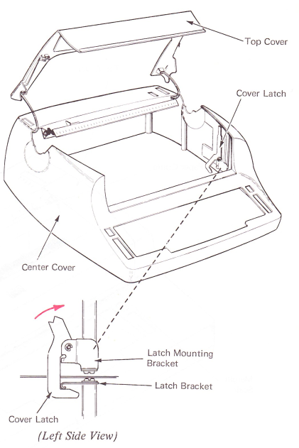
Figure 4 — Center Cover latches (Level 3)
The Level 3 bottom cover has the vent positioned in a slot at the rear. The rubber mounting to support the typewriter inside the case is also contained within the bottom cover (Figure 5).
The Level 1 and Level 2 center cover assemblies have the vent grille mounted in the rear by a plate. Slotted holes in the plate allow the vent to be removed without removing the plate from the center cover. The Level 1 bottom case is held in place by a screw at the center rear.
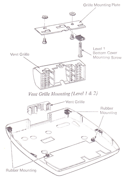
Figure 5 — Bottom Cover Rubber Mounting (Level 3)
The Level 2 bottom case is held in place by friction fit and does not use the rear mounting screw (Figure 6).
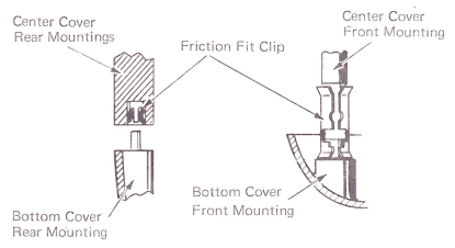
Figure 6 — Bottom Cover Mounting (Level 2)
MOUNTING BRACKETS
The machine mounting brackets are attached to the machine frame and are adjusted vertically. A latch lever (Figure 7) locks the machine to the rubber mounting foot on the left side of the machine (Figure 5).
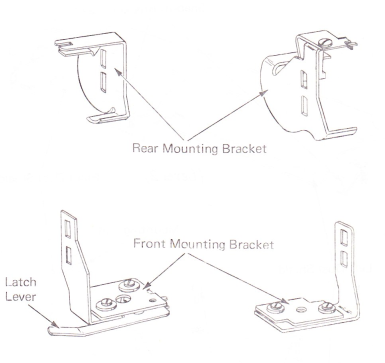
Figure 7 — Frame Mounting Brackets (Level 3)
The Level 1 and Level 2 cover assemblies are mounted to the machine by brackets attached to the center cover assembly by mounting plates. The machine is supported on rubber bushings attached to the mounting plates (Figure 8).
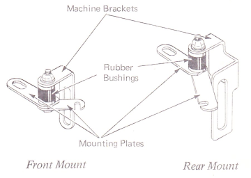
Figure 8 — Center Cover Frame Brackets (Level 1 & 2)
DUST SHIELDS
There are two levels of dust shields located just below the carrier (Figure 9). The Level 2 dust shields are plastic and fit into the power frame at the rear and into three mounting brackets at the front. The Level 1 dust shields are metal and are held in place by three screws and a nut.
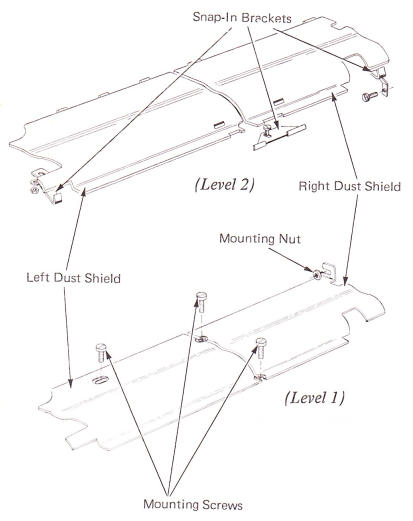
Figure 9 — Dust Shield