Selectric Resources
TABULATION (RB/S) OPERATIONAL THEORY
The tab mechanism on RB/S machines can operate with either 10 or 12 pitch using the same parts. This is because of a universal tab rack. The tab stops are spaced in such a way that the escapement pawl will re-enter the proper rack tooth correctly in either pitch (Figure 1).
The tab mechanism used in RB/S machines provides the operator with the same features as machines with NRB/S, but with two additional instructions:
1. The machine will not reliably tab from within one space of a set tab stop.
2. (Dual Pitch Only) Before switching pitch, all tab stops should be cleared and necessary tab stops reset after the pitch is changed.
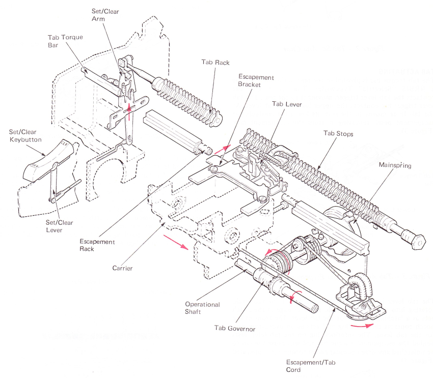
Figure 1 — Dual Pitch Tab
TAB SET AND CLEAR
The tab rack is rotated to set or clear a tab stop in the same way as NRB/S machines. However, the tab stops are both set and cleared by a lug on the tab set and clear bracket. On 10 pitch machines, and on dual pitch machines in the 10 pitch mode, the tab set and clear lug will set or clear the two closely spaced tab stops at the same time. On 12 pitch machines, and on dual pitch machines in the 12 pitch mode, it will set or clear them one at a time (Figure 2).
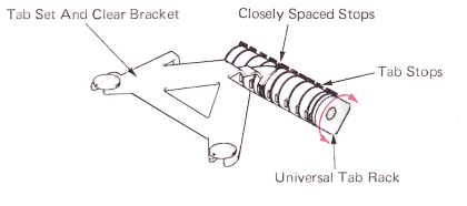
Figure 2 — Tab Set And Clear
TAB ACTUATING
The tab torque bar is pivoted to the rear in the same way as a NRB/S “Selectric” Typewriter. The tab torque bar contacts the tab lever trigger, moving it to the rear. The tab lever trigger lug contacts the upper lug on the tab lever. As the tab lever moves to the rear, its lower lug contacts the escapement pawl, removing it from the escapement rack (Figure 3).
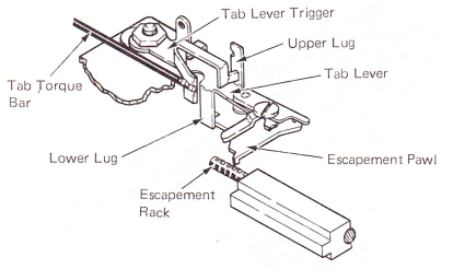
Figure 3 — Tab Actuating And Escpament Pawl Removal
The tab lever is latched by the latch lug of the tab latch, rotating into the latching notch. The rear edge of the notch acts as a latching surface for the tab lever. The front of the notch contacts the latch lug and acts as an overthrow stop for the tab lever. The interlock lug on the tab latch rests behind the escapement torque bar and will cause the tab to be unlatched any time the escapement torque bar is operated (Figure 4).
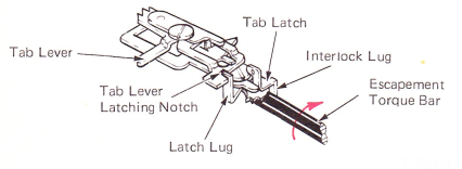
Figure 4 — Tab Lever Latching
The tab lever pawl is mounted to the tab lever by a shoulder screw. It pivots on the tab lever front-to-rear and is spring loaded toward the rear. This allows the tab lever to continue its rear movement even though the tab lever pawl contacts the end of a set tab stop. This will occur sometimes because of the universal tab stop spacing. A tab lever pawl adjusting plate is mounted to the tab lever, controlling the amount of tab lever pawl overlap on a set tab stop (Figure 5).
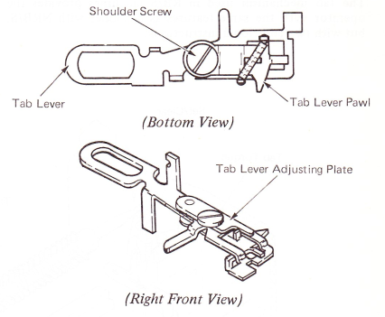
Figure 5 — Tab Lever Pawl Mounting
When the tab lever is latched out, the escapement pan is removed from the escapement rack and the carrier moves to the right. The tab lever pawl contacts a set tab stop, causing the tab lever to stop as the carrier continues to move to the right. After .020” (0.51 mm) of additional movement of the carrier, the escapement pawl drops from the lower lug on the tab lever and, under its spring tension, restores back into the escapement rack. Further movement of the carrier causes the tab lever to unlatch and restore to its rest position. The escapement pawl against the escapement rack tooth stops the carrier (Figure 6).
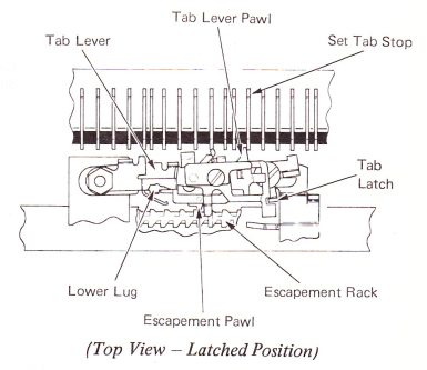
Figure 6 — Tab Operation
UNIVERSAL TAB STOP SPACING
The tab stops are spaced on the universal tab rack to work with both 10 and 12 pitch escapement racks. Figure 7 shows the tab lever pawl contacting a tab stop, if it were set, and approximately where the escapement pawl starts to enter the escapement rack tooth for that stop. Every 1/2 inch (5 teeth in 10 pitch and 6 teeth in 12 pitch) an escapement rack tooth, is common for both pitches; therefore, the tab stop spacing is repeated every 1/2 inch (Figure 7).
This is shown for example only. Keep in mind that the machine will not tab reliably from within one space of a set tab stop.
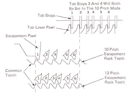
Figure 7 — Universal Tab Stop/Spacing Rack Teeth
ESCAPEMENT (RB/S)
In the RB/S escapement mechanism,the vertical position of the escapement pawl is critical. The pawl must be centered in the escapement rack within the opening in the escapement rail. An escapement pawl guide bracket is mounted above the escapement pawl. The escapement pawl guide lug extends down from the bracket and is formed under the escapement pawl to control its vertical movement. The escapement pawl vertical position is controlled by the vertical position of the rear of the carrier. which is adjustable. A diagonal mounting slot in the rear carrier shoe provides the adjustment. As the carrier shoe is adjusted left or right, the rear of the carrier is raised or lowered (Figure 8).
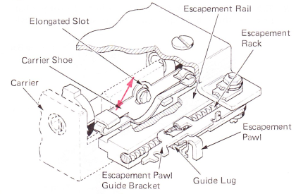
Figure 8 — Escapement Pawl And Carrier Shoe Mounting (Right Rear View)