Selectric Resources
TABULATION (NRB/S) OPERATIONAL THEORY
The purpose of the tab mechanism is to quickly move the carrier to the right to a desired position on the writing line. This is done by removing the escapement and backspace pawls from their racks and allowing the carrier to be pulled to the right under mainspring tension (Figure 1). When the carrier reaches a preset tab stop, the pawls are returned to their racks and the carrier is held in the new position.
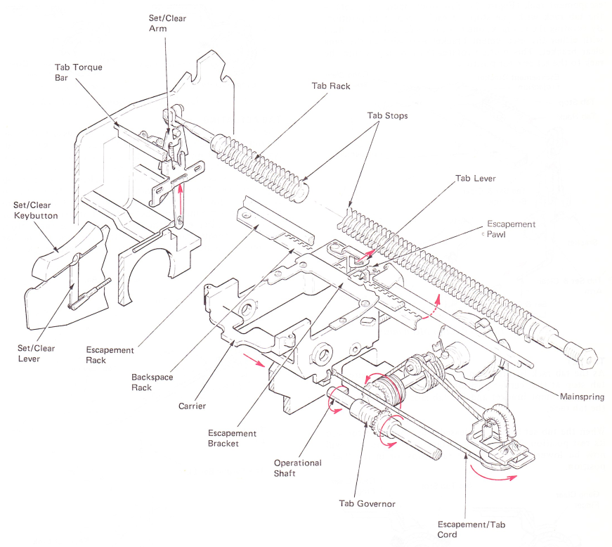
Figure 1 — Tab Mechanism
TAB SET AND CLEAR
The tab set/clear button is located at the left side of the keyboard (Figure 2). A set and clear link extends toward the rear from the set/clear keybutton and is connected to the tab set/clear arm. The tab set/clear arm is mounted on a bracket in such a way that it will toggle front or rear at the top. The tab set/clear bellcrank is mounted on the left end of the tab rack and its lower extension fits into a notch in the top of the tab set/clear arm.
When the set/clear keybutton is depressed, motion is transferred through the set and clear link, the tab set/clear arm, and the set/clear bellcrank to rotate the tab rack.
The tab rack is located parallel to and just to the rear of the escapement rack (Figure 2). Tab stops operate in slots in the tab rack with one stop for each escapement position. By rotating the tab rack, one tab stop is forced into contact with either the escapement bracket extension or the gang clear bracket. This motion rotates the tab stop within the rack to the set or clear position.
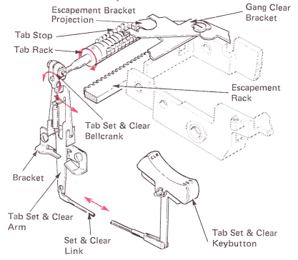
Figure 2 — Tab Set & Clear Mechanism
TAB SET
As the tab rack is rotated in the set direction (Figure 3), a tab stop at that carrier position contacts the extension on the escapement bracket and the tab stop is rotated within the tab rack.
When the tab set button is released, the tab rack restores to its rest position. The working surface of that tab stop will now be lower than the other tab stops, or in the “set” position.
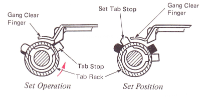
Figure 3 — Tab Set Operation (Left Side View)
TAB CLEAR
The set tab stop may be cleared by depressing the rear of the tab set/clear keybutton, which rotates the tab rack in the opposite direction (Figure 4). As the tab rack is rotated, the set tab stop will contact the gang clear finger and be rotated within the rack to its cleared position.
Tab stops may be cleared one by one or gang cleared. To gang clear, the carrier is positioned to the far right of the writing line, the tab clear keybutton is held depressed, and a carrier return operation is started. The set tab stops are moved back to their rest position by the gang clear finger as the carrier is returned to the left-hand margin.
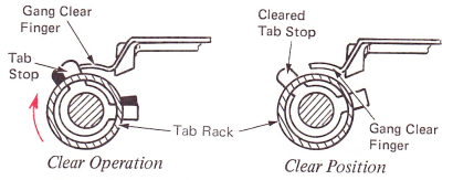
Figure 4 — Tab Clear Operation (Left Side View)
TAB ACTUATING
The tab mechanism is activated by depressing the tab keybutton, located at the upper left corner of the keyboard. As the keylever pivots on its fulcrum rod, the lower extension of the keylever moves to the rear (Figure 5). This extension is connected to the tab bellcrank by the tab keylever link. The tab bellcrank is connected to an arm on the tab torque bar by the tab torque bar link. The tab torque bar is mounted parallel to the print shaft at the rear of the carrier. Depressing the keylever will cause the bottom of the tab torque bar to pivot to the rear. The torque bar will remain pivoted to the rear until the keylever is released.
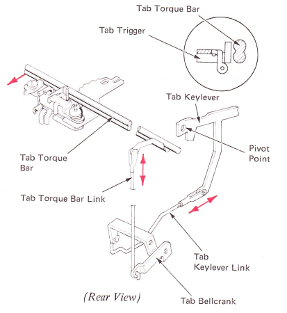
Figure 5 — Tab Actuating
TAB LEVER OPERATION
Pawl removal begins when the torque bar pushes against the tab trigger. The lower lug of the tab lever trigger pushes the tab lever to the rear (Figure 6).
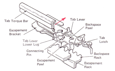
Figure 6 — Tab Lever Operation (Right Front View)
As the tab lever is moved to the rear, its lower lug contacts the backspace and escapement pawls and moves them to the rear out of their racks (Figure 7), When the escapement pawl just clears its rack, it is pulled to the right by the pawl spring. The backspace pawl will move up to the right an equal amount because of the stud connection between the escapement pawl and the backspace pawl.
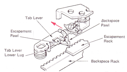
Figure 7 — Tab Lever Operation (Left Front Backspace View)
TAB LATCHING
As soon as the escapement and backspace pawls are removed from their racks, the carrier will be allowed to move to the right under mainspring tension.
As the tab lever continues to move to the rear, the tab lever latch engages a notch in the tab lever to latch the mechanism in its operated position, and to prevent the tab lever from overthrowing into the tab rack. With the tab lever latched, the tab pawl (mounted on the tab lever) is now in a position to contact the next set tab stop as the carrier moves to the right (Figure 8).
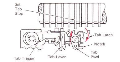
Figure 8 — Tab Latching Tab Lever Operation\(Top Pawl View)
EARLY LEVEL MACHINES
As the pawls move to the right, they are also moved further to the rear by the tab lever, The tab lever will continue to be moved by the trigger until the trigger is limited by the tab overthrow stop. When the keybutton is released, the tab lever will be held to the rear by the tab lever latch (Figure 9).
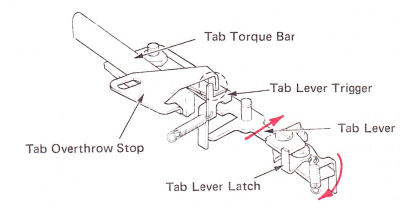
Figure 9 — Tab Overthrow Stop
TAB GOVERNOR
The carrier speed during a tab operation is controlled to prevent parts breakage or bouncing to the wrong position. The tab governor controls the carrier speed by limiting the speed at which the mainspring tension can turn the escapement cord drum to wind up the tab/escapement cord (Figure 10).
The gear of the escapement cord drum engages with the tab governor pinion gear. The governor pinion gear mounts on the operational shaft between two collars that are attached by setscrews to the operational shaft. The left collar and the pinion gear have hubs that are connected by a clutch spring. The clutch spring is wound so that it slips when the pinion gear is held still and the operational shaft is turning (Figure 10).
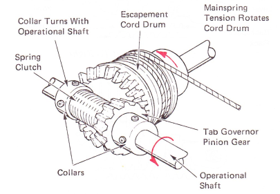
Figure 10 — Tab Governor Mechanism
During a tab operation, the escapement cord drum rotates the tab pinion gear in the same direction as the operational shaft. As soon as the rotational speed of the pinion gear tries to moves faster than the operational shaft. the clutch spring tightens around the two hubs, locking the pinion gear and the collar together. Since the collar is attached to the operational shaft, the speed of the escapement cord drum will be limited to the speed of the operational shaft.
TAB UNLATCHING
As the carrier moves to the right, the tab lever pawl contacts a set tab stop and the tab lever stops moving. However, the carrier and pawls will continue moving to the right because of the elongated mounting hole in the tab lever. Continued movement of the carrier and pawls past the stopped tab lever will cause the escapement pawl to slide off the lug on the escapement lever. The escapement pawl will then be free to restore back into the rack under its spring load. The backspace pawl does not have a notch. so it will remain held by the escapement lever lug (Figure 11).
Further movement of the carrier will cause the tab lever to slip off its latch. When the tab lever restores, it will allow the backspace pawl to reenter its rack. Although all parts have been unlatched and restored to their rest positions, the carrier has not stopped. When the escapement pawl was released from its rack, its spring tension held the escapement pawl fully extended to the right in its elongated mounting hole, and against the left side of the pawl mounting stud. After the escapement pawl enters the rack, its movement to the right is stopped by a rack tooth. The carrier continues to move to the right until the pawl mounting stud contacts the right side of the elongated slot in the escapement pawl and stops.
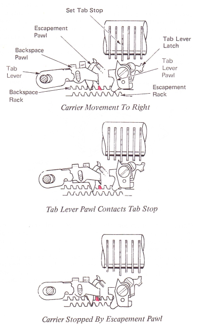
Figure 11 — Tab Unlatching Operation (Top View)
TAB TRIGGER
The function of the tab trigger is to allow the tab lever to restore at the end of a tab operation if THE TAB KEYBUTTON IS STILL HELD DEPRESSED BY THE OPERATOR. The tab lever and tab trigger are designed so that when the tab lever is moved to the left after contacting a set tab stop, it will slide off the trigger lug which was holding it to the rear. With the trigger no longer holding the tab lever out, it is free to restore. When the tab keybutton is released, the tab trigger will restore to its rest position. At this time, the tab lever will move quickly to the right under spring load, resetting the tab lever behind the tab trigger lug.
Also, the tab lever moving to the right will reset its lug in front of the escapement pawl in a position to move it out of the rack on the next tab operation (Figure 12).
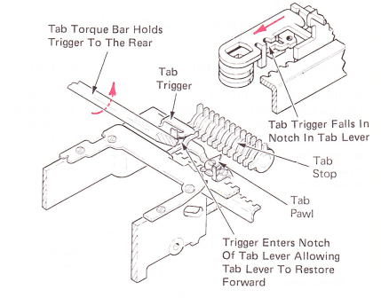
Figure 12 — Tab Lever Trigger Operation
TAB INTERLOCK
The tab interlock prevents the tab lever from being latched to the rear during a carrier return operation. If the tab lever were allowed to latch, the tab lever pawl could strike the right side of a set tab stop during a carrier return operation and lock the carrier. To prevent this from happening, the tab lever latch has a lower lug extending behind the escapement torque bar. When the escapement torque bar is pivoted, the tab lever latch will be rotated out of its latching position, preventing the tab lever from being latched out. The escapement torque bar pivots during a carrier return operation, spacebar operation, or print escapement operation (Figure 13).
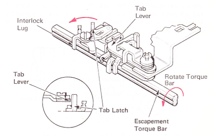
Figure 13 — Tab Interlock
CARRIER RETURN/TAB INTERLOCK
The carrier return tab interlock allows a tab operation to go before or unlatch a carrier return operation after the carrier return operation has begun. Pressing the tab keybutton during a carrier return operation will pivot the tab torque bar to the rear so that a lug on its right end will pivot the carrier return/tab interlock extension of the carrier return latch keeper. When the carrier return/tab interlock lever is pivoted by the torque bar, the extension will unlatch the carrier return (Figure 14).
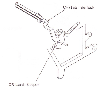
Figure 14 — Carrier Return/Tab Interlock (Right Front View)