Selectric Resources
OPERATIONAL CAM FOLLOWER ROLLER
A replaceable spacebar and carrier return cam follower roller is available. Removal of the roller and the roller rivets is performed with special tools.
NOTE: Cam follower removal tool must be lubricated to reduce friction. Failure to lubricate tool will make it hard to turn handle. If handle continues to bind, add washer (P/N 1117394, in parts packet no. 8) between handle and tool body.
1. Remove escapement trip link.
2. (Carrier Return) Remove index link.
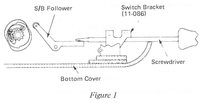
(Spacebar) Move machine forward in bottom cover. Insert screwdriver under switch bracket and over cam follower, as shown, to raise cam follower roller (Figure 1).
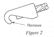
NOTE: Installation of the removal tool may be hard. This condition can be reduced by one of the following:
a. Use a grinder to remove part of hook as shown (Figure 2).
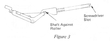
b. Tool can be disassembled allowing installation of hook over roller as shown. If this procedure is used, tighten shaft finger tight against roller at this time.
CAUTION: If shaft is not touching roller, it is possible that the cam follower arm will break; however, tightening shaft too tight against roller makes removal of the roller from the tool hard, and may result in breakage of the screwdriver slot. If shaft is tightened too much, the handle may be loosened until threaded part is flush with slotted end of shaft. This will provide support to extensions of shaft while loosening.
3. With tool installed as shown (Figure 4), ensure shaft is touching roller to lock roller in place. (This may be done with tool assembled, using the screwdriver slot in end of shaft.
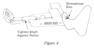
CAUTION: Do not tighten shaft too much; review step 2b.) Lock tool against print shaft and tighten handle until roller pulls out of follower arms.
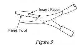
4. If rivet heads remain in arms, install rivet tool on one side of duckbill pliers and punch rivet out. A piece of paper may be placed inside the rivet tool to help hold tool on duckbills (Figure 5).
Install replaceable roller as shown (Figure 7).
IMPORTANT: Lubricate all replaceable parts with No. 10 oil before installation.
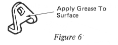
5. (Carrier Return) The suggested procedure is as follows: Install sleeve inside roller. Apply grease on locking plate (Figure 6).
Align flats on sleeve with hole in locking plate and press against roller. While holding roller with scissor clamps, lower complete assembly between follower arms. LH arm should be in slot of locking plate. Install one “C” clip on pivot shaft and install pivot shaft through complete assembly. Install remaining “C” clip (Figure 7).
NOTE: Roller may also be installed using disassembled tool as shown in Figure 3.
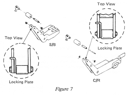
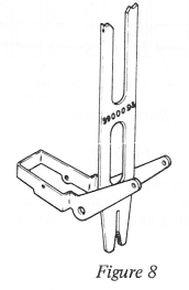
(Spacebar) The suggested procedure is as follows: Install typebar aligning tool between cam follower arms (Figure 8). Apply grease to locking plate and install over LH follower arm and align holes. Install pivot shaft through roller. While holding roller in place between follower arms with scissor clamps or tool as shown in Figure 3, align flats on end of shaft with slot in locking plate and remove aligning tool. Install nuts on shaft (Figure 7).
CAUTION: Do not tighten too much.
NOTE: Locking plate must be installed on all cam followers to ensure pivot pin does not rotate, and should be installed on the LH follower arm.
6. (Spacebar) Replace existing tab cord idler pulley with smaller pulley to ensure there is no interference between nut and pulley.
7. Replace escapement trip link and index link.
8. Roller pivots must be lubricated.
9. Check operational interposer restoring bail adjustment.
10. Check operational latch height adjustments.
11. (Carrier Return) Check carrier return overthrow.
12. (Carrier Return) Check all index adjustments.
13. (RB/S) Check backspace motion adjustments.
14. Check escapement trip link.