Selectric Resources
OPERATIONAL CAM FOLLOWER REPLACEMENT
When necessary to replace the carrier return or spacebar cam follower, replace both.
The suggested replacement procedure is as follows:
1. Unplug machine.
2. Remove escapement trip link.
3. This procedure does not require removal of the operational shaft; however, it may be removed at this time.
4. Disconnect carrier return and spacebar cam follower restoring springs.
5. Remove ON/OFF switch from mounting bracket.
6. (RB/S) Remove index interlock link.
7. Disconnect lower index link from multiplying lever.
8. Remove the spacebar (NRB/S), carrier return and backspace latch springs.
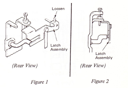
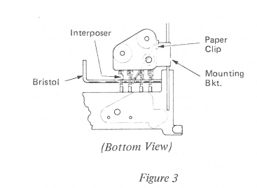
9. Loosen carrier return latch assembly setscrew and move latch assembly toward center of machine (Figure 1) and pivot up as shown (Figure 2).
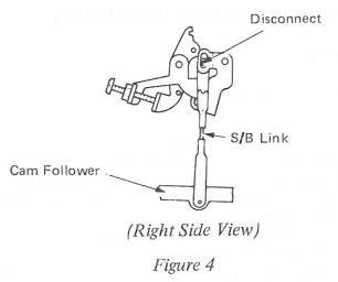
10. Install splined wrench through holes in interposers and attach to RH mounting bracket with paper clip (Figure 3).
11. (Correcting) Disconnect correcting keylever link and spring from mode latch.
12. Remove all “C” clips (8) from pivot shaft and remove shaft from right.
13. Remove carrier return cam follower (from front or rear).
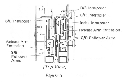
14. (RB/S) Disconnect Spacebar link at top clevis (Figure 4).
15. Remove Spacebar cam follower from front of machine.
16. Replace carrier return cam follower:
a. (RB/S) Position the index, carrier return and backspace interposers between the cam follower arms (Figure 5).
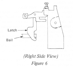
b. (RB/S) Position the carrier return and backspace latches to the front of the cam follower bail (Figure 6).
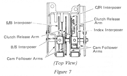
(NRB/S) Position the index and carrier return interposers between the cam follower arms (Figure 7).
c. Position the clutch release arm to the right of the carrier return interposer (Figures 5 and 7).
17. Install pivot pin through right-hand cage plate, carrier return cam follower and clutch release arm.
18. Install spacebar cam follower:
a. (RB/S) Spacebar link may be installed with the cam follower. With cam follower in place, hook clevis to bellcrank.
b. (RB/S) Position the spacebar interposer and clutch release arm between the cam follower arms with the clutch release arm to the right of the interposer (Figure 5).
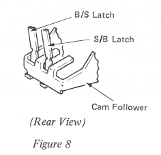
c. (NRB/S) Position the backspace and Spacebar interposers and clutch release arm between cam follower arms (Figure 7) with the latches in their slots and under the cam follower bail (Figure 8). The clutch release arm extension should be between the interposers (Figure 7).
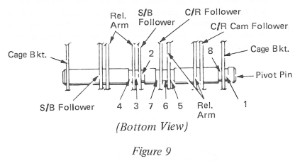
19. Install the pivot pin through the spacebar cam follower and clutch release arm and install the “C” clips in the following order (Figure 9). Number 8 is a bias “C” clip.
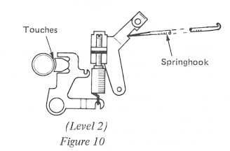
20. Position the carrier return latch assembly in place and with pusher end of springhook, push arm against carrier return spring and tighten setscrew (Figure 10).
21. Install index link to multiplying lever. (Rear hole is for 36 tooth only.)
22. Hook spacebar (NRB/S), carrier return and backspace latch springs. (This is done by half cycling the operational cam while holding latch from under bail. Latches may now be easily accessed.)
23. Reconnect carrier return and spacebar cam follower restoring springs.
24, Replace index interlock link.
25. Replace ON/OFF switch.
26. Reconnect correcting keylever link and spring.
27. Remove paper clip and splined wrench.
28. Replace and adjust escapement trip link.
29. Adjust the index interlock link (RB/S).
30. Adjust the index interlock paddle (RB/S).
31. All index adjustments should be made at this time.
32. Adjust spacebar link.
33. Latch height should be adjusted for proper clearance between latches and bails with interposers released.
34. Adjust carrier latch overthrow.
35. Adjust correcting keylever link.
36. Adjust carrier return shoe clearance.