Selectric Resources
Half Backspace Adjustments
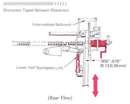
1. Lower Half Backspace Link (Level 1) — Place the machine in the 10 pitch mode. Adjust the lower half backspace link so that characters typed when half backspace is operated will be centered between characters typed normally.
NOTE: The switch pitch gear must be adjusted left to right to have .005"-.010” (0.13-0.25 mm) clearance between the escapement rack bearing plate and the switch pitch gear.
2. Switch Pitch Gear (Levels 2 And 3) — Adjust the escapement rack gear flush against (no clearance) the cam lever with the escapement rack in the 12 pitch mode.
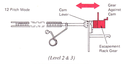
3. Half Backspace Collar (Levels 2 And 3) — With the escapement rack in 12 pitch, position the escapement rack to ensure the teeth are vertical. Adjust escapement rack gear for minimum clearance between the gear and cam lever.
Adjust the half backspace collar so it contacts the top extension on the escapement rack bracket after approximately .045” (1.14 mm) movement of the escapement rack. Readjust so that characters typed when the half backspace is operated will be centered between characters typed normally.
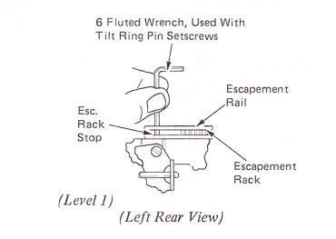
NOTE: Setscrew should be toward the front of the machine in the 12 pitch mode.
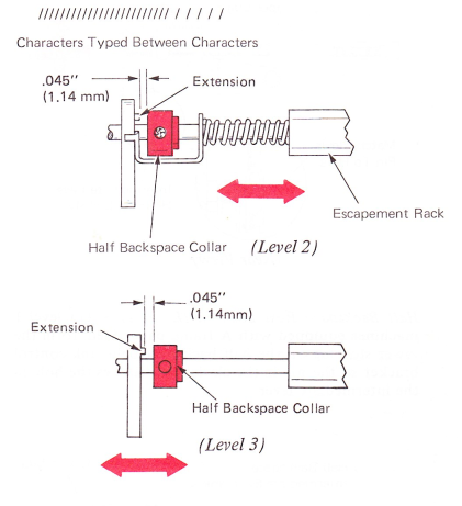
The .045” (1.14 mm) adjustment can be made by inserting a 6 fluted wrench (used to adjust the Level 1 tilt ring setscrews) between the right end of the escapement rack, and the stop pin in the right end of the escapement rail.
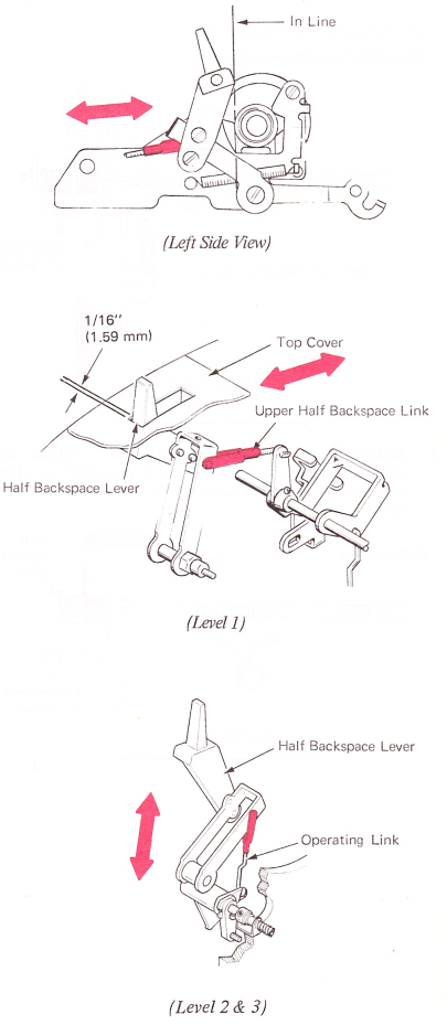
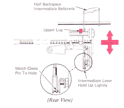
4. Half Backspace Rest Position (Level 1) — Hold the rear of the half backspace intermediate lever up lightly. Form the upper lug on the half backspace intermediate bellcrank so the pin in the clevis just matches the hole in the intermediate lever. This ensures that the escapement rack will rest against the pin in the escapement rail when the half backspace mechanism is at rest.
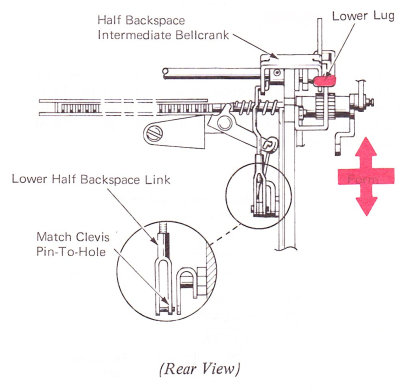
NOTE: On machines prior to “A frame” paper feed, take off the lower half backspace link.
Half Backspace Rest Position (Level 1) — On level 1 machines equipped with A frame paper feed, form the lower stop lug on the half backspace bellcrank control bracket so the pin in the clevis just matches the hole in the intermediate lever.
5. Half Backspace Lever (Level 1) — Adjust the upper half backspace link so the front edge of the half backspace lever is in line with the rear edge of the platen bearing.
After the machine is placed in the covers, adjust the link so that the lever clears the end of the cover slot by about 1/16” (1.59 mm) when it is in the operated position,
On level 2 and 3 machines, adjust the operating link for this condition.