Selectric Resources
ESCAPEMENT (NRB/S AND RB/S) ADJUSTMENTS
NOTE: Before any adjustments are performed in this section, switch pitch adjustments must be correct.
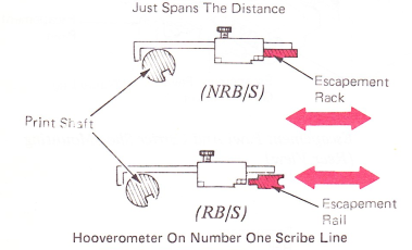
1. Escapemenr Rack (NRB/S And RB/S) — Rotate the print shaft so the keyway is down and adjust the escapement rail front to rear so the Hooverometer will just reach the distance from the print shaft to the escapement rail with the Hooverometer on the No. l scribe line using the following procedure:
a. Loosen first three rail mounting screws from left end and adjust the left end. After adjusting the left end, tighten the first rail mounting screw. It is important that this screw is tight to prevent loss of left-to-right position of the rail when adjusting the right end.
b. Loosen the remaining screws on the right end. Using the Hooverometer, adjust the center and tighten. center screw. At this point, it may be necessary to bend the right end of the rail to
match the left and center. Adjust the rail using the Hooverometer and tighten screws. This procedure will ensure the escapement rail is not bent and is parallel to the print shaft.
2. Escapement Rack Guide — Loosen the two escapement rack guide screws and adjust the guide up and down, and front to rear so the guide will be centered around the escapement rack. The left end of the escapement rack is held in place by the escapement rack guide.
NOTE: This adjustment should be done with the switch pitch selector gear removed from contact with the escapement rack gear. Readjust the escapement rack gear after making guide adjustment.

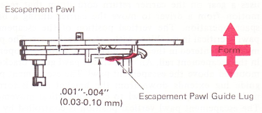
3. Escapement Pawl Guide Lug (RB/S Only) — Form the escapement pawl guide lug for .001”-.004” (0.03-0.10mm) clearance between the lug and the escapement pawl.
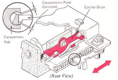
4. Carrier Shoe (RB/S Only) — Adjust the carrier shoe left or right to center the escapement pawl in the opening of the escapement rail.
This adjustment may be observed by applying grease on the escapement rail approximately 2” (50.8 mm) from the right end. Type or space to track the escapement pawl through the grease. Carrier return and look down the rack from the right end and Observe the track left by the escapement pawl in the grease. The track should be centered in the rack.
NOTE: The front carrier support adjustment must be checked before making this adjustment.
After making this adjustment, check carrier movement across the full writing line. The carrier shoe could tilt when tightening the mounting screw and cause the carrier to bind.
5. Carrier Buffer — Adjust the carrier buffer front-to-rear to get .001”-.002” (0.03-0.05 mm) between the carrier buffer and the escapement rail. (Some machines may not have the carrier buffer and will not require this adjustment.)
6. Escapement Bracket (NRB/S) — Position the escapement bracket parallel to the tab torque bar with .011”-.017” (0.28-0.43 mm) clearance on Level 1 and .010”-.012” (0.25-0.30 mm) on Level 2.
NOTE: This adjustment affects the tab adjustments.

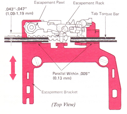
Escapement Bracket (RB/S) — Position the escapement bracket front to rear so the front left side of the escapement pawl clears an escapement rack tooth by .043”-.047” (1.09-1.19 mm). This clearance can be seen from the bottom with the carrierjust to the right of center.
The bracket must be parallel to the tab torque bar within .005” (0.13 mm). This parallel condition must be observed from the top.
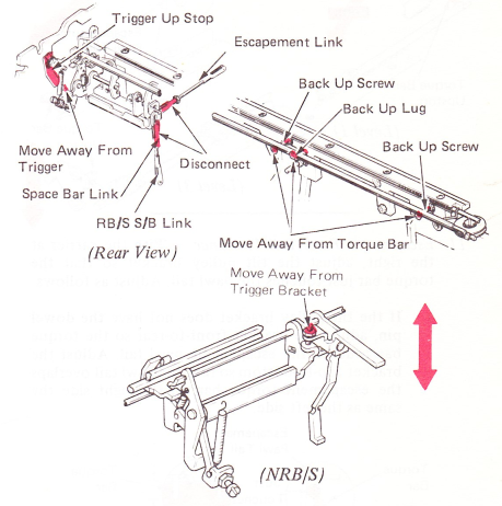
7. Torque Bar (Preliminary) — Move the torque bar backup screws away from the torque bar. Move the trigger upstop out of the way and disconnect the spacebar link (RB/S only) and move the spacebar latch lever screw away from the escapement trigger bracket (NRB/S). Disconnect the escapement link.
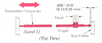
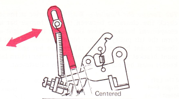
8. Escapement Torque Bar (Level I, NRB/S) — Adjust the escapement torque bar .005”-.010” (0.13-0.25 mm) end play with the escapement trigger centered on the escapement bar lug.
9. Pawl Mounting Stud (Preliminary) — Move the pawl mounting stud as far away from the escapement torque bar as possible.

10. Torque Bar Upstop (Preliminary) — With the carrier at the left, adjust the torque bar upstop so the torque bar just touches the pawl tail.
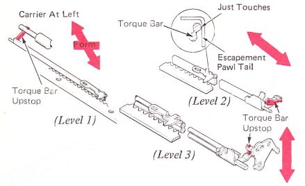
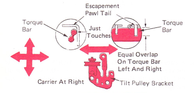
11. Escapement Pawl Tail Clearance ~ With the carrier at the right, adjust the tilt pulley bracket so that the torque bar just touches the pawl tail. Adjust as follows:
a. If the tilt pulley bracket does not have the dowel pin, adjust the bracket front-to-rear so the torque bar touches the escapement pawl tail. Adjust the bracket top-to-bottom so that the pawl tail overlaps the escapement torque bar on the right side the same as the left side.
b. If the tilt pulley bracket has a pin in it, it is possible to drive the pin in and adjust as in step 11a.
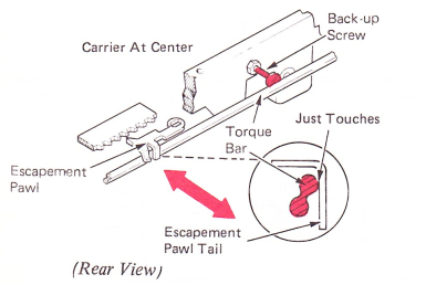
12. Center Torque Bar Backup Screw (Final) — Move the carrier to the center and adjust the center backup screw so that the escapement torque bar touches the escapement pawl tail.
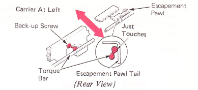
13. Left Torque Bar Backup Screw (Final) — Adjust the left torque bar backup screw to just touch the escapement torque bar.
14. Torque Bar Upstop (Final) — Adjust the torque bar upstop to get a clearance of .007”-.012” (0.18-0.30 mm) between the torque bar and the pawl tail after the following condition is met: Move the carrier to the left, center and right. Ensure the escapement torque bar is just touching the escapement pawl tail the whole length of the rail.
NOTE: Proper adjustment of machines with a torque bar upstop screw can be done by ensuring the escapement torque bar is just touching the escapement pawl tail at the left, center, and right and then backing the torque bar upstop screw out one full turn. This will give the proper clearance.

15. Pawl Mounting Stud (Level 1) — Adjust the pawl mounting stud around to get .001” (0.03 mm) clearance between the mounting stud and the front of the escapement torque bar. Keep the eccentric in the left half of the turn.
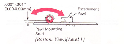
Pawl Mounting Stud (RB/S) — Adjust the pawl mounting stud to get .000”-.001” (0.00-0.03 mm) clearance between the mounting stud and the front of the escapement torque bar. Keep the eccentric in the right half of the turn.
NOTE: The nut is a left-hand thread. Copper coloring is an industry standard for identification of a left-hand thread.
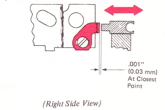
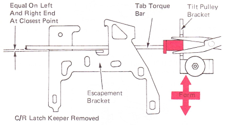
16. Tab Torque Bar Parallel — With the carrier at the left, check the clearance between the tab torque bar and escapement bracket. Move the carrier to the right and form the tilt pulley bracket lug so the clearance at the closest point between the tab torque bar and escapement bracket matches left side. The carrier return latch keeper must be removed to make this adjustment.
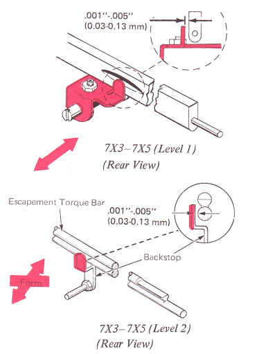
17. Torque Bar Backstop — Adjust the backstop front-to-rear to get .001”-.005” (0.03-0.13 mm) clearance between the stop and the rear of the torque bar.
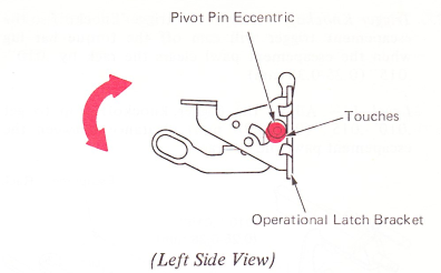
18. Pivot Pin Eccentric (Early Level Machine Only) — Adjust the eccentric collar with the high point up so that it touches the operational latch bracket. This prevents the pivot pin from ending during a print escapement operation. On long carriage machines, the eccentric should also be adjusted laterally on the pivot pin for .002”-.005” (0.05-0.13 mm).
NOTE: The eccentric may require readjustment if the rest position of the pivot pin is changed during carrier return adjustments.
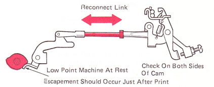
19. Escapement Cam — Reconnect the escapement link and adjust the escapement cam on the filter shaft so the cam follower roller is resting at the start of the low point of the cam with the machine at rest.
On machines equipped with the early level spacebar lockout mechanism, the lockout cam adjustment must be checked each time the escapement cam adjustment is changed. Changing the position of the escapement cam could allow the lockout cam to keep the spacebar mechanism from operating.
NOTE: Escapement should occur just after print.
World Trade (9XX) — Escapement should occur after print when the distance between typehead and the platen (impression control at 5) is .042”-.060” (1.07-1.52 mm).
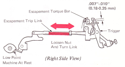
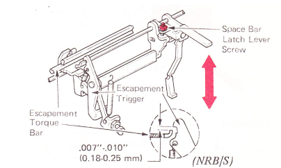
20. Escapement Trip Link — With the machine latched at rest, adjust the escapement trip link to get .007”-.010” (0.18-0.25 mm) clearance between the hook on the trigger and the extension on the escapement torque bar. Be sure the trigger lever upstop and spacebar motion adjustments are not limiting the trigger.
21. Trigger Knockoff — Adjust the trigger knockoff so the escapement trigger will earn off the torque bar lug when the escapement pawl clears the rack by .010”-.015” (0.25-0.38 mm).
Level 1 — Adjust the trigger knockoff stop to get .010”-.015” (0.25-0.38 mm) clearance between the escapement pawl and the rack.

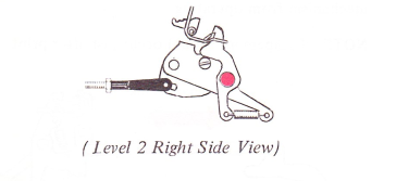
Level 2 — Adjust the eccentric to get .010”-.015” (0.25-0.38 mm) clearance between the escapement pawl and the rack.
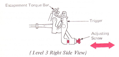
Level 3 — Adjust the knockoff adjusting screw to get .010”-.015” (0.25-0.38 mm) clearance between the escapement pawl and the rack.
22. Trigger Lever Upstop — With all parts at rest, adjust the trigger lever upstop vertically to get .001”-.005” (0.03-0.13 mm) clearance between the upstop and the trigger lever.
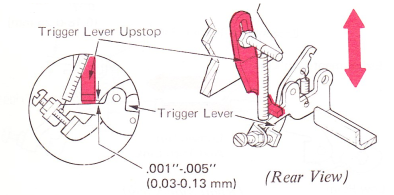
Make sure the trigger upstop is centered between its restoring spring and the trigger mounting lug.
23. Spacebar Motion — Adjust the spacebar motion using the proper procedure:
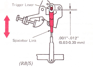
a. RB/S — Adjust the spucebar link for .001”-.012” (0.02-0.30 mm) between the clevis pin and the bottom of the slot in the trigger lever.
b. NRB/S — Adjust the spacebar latch lever screw to get a .007”-.010” (0.18-0.25 mm) clearance between the escapement trigger and the escapement torque bar.
24. Escapement Rail Parallel To Escapement Torque Bar (Final Check) — The following procedure may be used to ensure the escapement rail, print shaft and escapement torque bar are parallel. With the machine on, pull the escapement trigger down until the escapement pawl just clears the rack. While holding the carrier with the left hand, move the carrier left and right the full length of the writing line several times, listening to the pawl drag on the tips of the escapement rack. A great difference in sound between the left, center and right ends means that the torque bar and escapement rail are not parallel. Check that the escapement rail is parallel and the escapement pawl tail clears the escapement torque bar by .007”-.012” (0.18-0.30 mm) across the writing line, Readjust the necessary adjustments to get this condition.
When all adjustments are correct, the carrier should space correctly when slight pressure is put on the left side of the carrier during a repeat spacebar or repeat underscore operation.
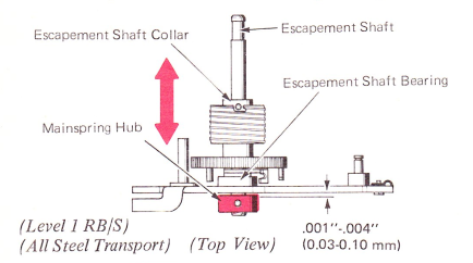
25. Mainspring Hub — Level 1 — (RB/S Only) — Adjust the mainspring hub for .001”-.004” (0.03-0.10 mm) end play of the escapement shaft in the rear escapement bearing. This adjustment should be made with the escapement shaft collar loose. Check the carrier return and tab pinion backlash after making this adjustment.
26. Escapement Shaft End Play —
a. Dual Transport And All Nylon Transport — Adjust the carrier return drum front to rear to get minimum end play and no binds, with the play removed in the escapement shaft toward the front.

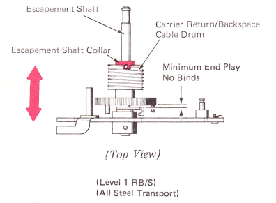
b. All Steel Transport — Adjust the escapement shaft collar for .001”-.004” (0.03-0.10 mm) end play of the carrier return/backspace cable drum on the escapement shaft.
NOTE: Check the carrier return and tab pinion backlash adjustments after making this adjustment.
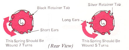
27. Mainspring — Adjust the mainspring for 1/2-3/4 lb. (226.8-340.2 g) of tension as the carrier tabs through the right-hand margin.
Manually latch the carrier return mechanism and rotate the turning wheel (while counting the revolutions of the escapement shaft) until the mainspring is wound the proper number of turns.
28. Idler Pulley Eccentric — Adjust the eccentric mounting stud for the front idler pulley so that the pin is above center on the eccentric. The pin should be turned toward the left slightly.

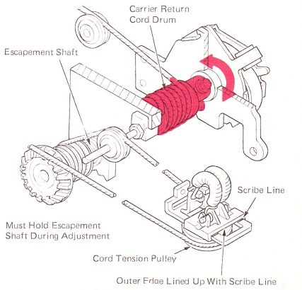
29. Cord Tension (Dual Transport And All Nylon Transport) — With the cords properly wound, adjust the carrier return cord drum so that the outer edge of the nylon pulley bracket lines up with the mark on the mounting bracket.
CAUTION: Be sure to remove all end play from the escapement shaft before tightening the carrier return cord drum. End play is removed by holding the escapement shaft forward while the cord drum is moved to the rear against the rear bearing. Hand or power cycle, then recheck adjustment with the carrier at the far right-hand margin.
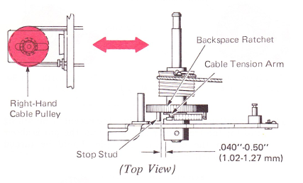
30. Transport Cable Tension (All Steel Transport) — Adjust the right-hand cable pulley left or right so the cable tension arm clears the stop stud on the backspace ratchet by .040”- .050” (1.02-1.27 mm).
NOTE: If the right-hand cable pulley reaches either limit of the adjustment slot, the rotational position of the tab/escapement cable drum must be changed on the escapement shaft.