Selectric Resources
DUAL TRANSPORT CHANGE
Change from the steel cable transport system to the dual transport system is possible without removing the backplate assembly.
1. Remove covers, platen, deflector and RH dust shield.
2. Remove switch from switch bracket.
3. Remove carrier return cable and tab cable.
4. Remove mainspring.
5. Remove carrier return shoe bracket.
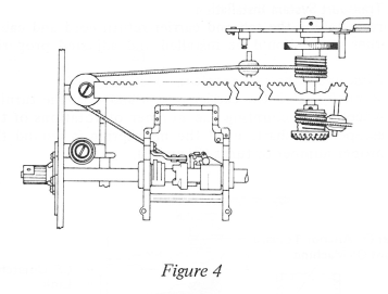
6. Remove escapement shaft. This can be done without removing the backplate. Break off the cable tension arm (Figure 1). Hold the tension arm with a screwdriver and turn the escapement shaft (with gas pliers). This may damage the escapement shaft hub, which will be replaced with the new level.
This process breaks out the D slot in the tension arm and will allow removal of the escapement shaft from the rear of the machine after setscrews are loosened in the tab drum and collar.
7. Remove the backspace driver.
8. Remove the backspace drum through the hole in the bottom of the power frame.
9. Remove the cord anchor bracket.
10. Remove the transport pulley bracket and pulley.
11. Remove the tab cord idler pulley.
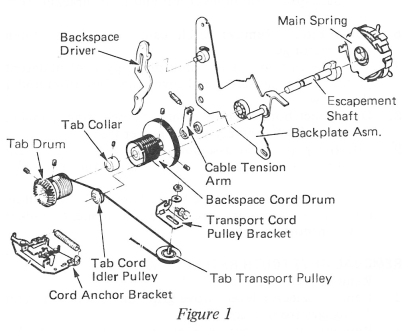
Installation of the dual transport parts can be done by reversing the removal procedure (Figure 2). Use the appropriate adjustment section for the adjustment of these components. Also be sure to install the driver mounting stud with the head against the backplate. Installation of the carrier return steel cable and the tab cord is reviewed below:

Dual Transport System Installation:
Before installing the tab and carrier return cord and cable, all other parts should be installed and adjusted properly.
1. Disconnect the carrier return unlatching link.
2. Manually latch the carrier return and turn the turning wheel while cunting the number of rotations of the escapement shaft, until the mainspring is wound the proper number of turns (Figure 3).
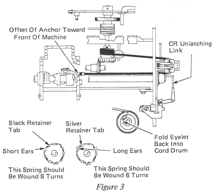
3. With the carrier all the way to the left, connect the tab cord to the carrier and position the cord through the right power frame and around the transport pulley; then connect it to the front drum (Figure 3). It is not necessary to wind the cord around the drum. With the cord attached to both ends, unlatch the carrier return and guide the cord on the drum while rotating turning
wheel. (This will wind the rest of the cord on the drum.) Then place the cord on the cord idler pulley (Figure 1).
4. Turn machine on and space or tab the carrier over the operational shaft area for easier installation of the carrier return cable. Turn the machine off and be careful not to backspace or carrier return because it will unwind the tab card. Next, loosen the setscrews in the backspace drum. With the machine off, cycle a backspace until the driver engages the ratchet. This will
help in the installation of the carrier return cable.
5. Attach the cable to the anchor bracket. (Use the fork end of a springhook.) Run the cable around the pulleys and tilt machine up. Hook the cable on the backspace drum and hold in position while rotating ratchet to wind the extra cable on the drum. This can be done by releasing the driver from the drum while holding and rotating the drum with the same hand; at the same time hold tension on the cable with a springhook from the left end of the machine. Do not position the cable around the front pulley and take up all extra cable and then tighten the backspace drum. Hook the cable over the front pulley and check for proper adjustment of the transport pulley.
6. Connect carrier return unlatching link.
7. Perform a functional check